Upgrading my home server
At the end of last year I decided it was time to upgrade my home server. I built it back in 2013 as an all-in-one device to be my only always-on machine, with some attempt towards low power consumption. It was starting to creak a bit - the motherboard is limited to 16G RAM and the i3-3220T is somewhat ancient (though has served me well). So it was time to think about something more up to date. Additionally since then my needs have changed; my internet connection is VDSL2 (BT Fibre-to-the-Cabinet) so I have an BT HomeHub 5 running OpenWRT to drive that and provide core routing/firewalling. My wifi is provided by a pair of UniFi APs at opposite ends of the house. I also decided I could use something low power to run Kodi and access my ripped DVD collection, rather than having the main machine in the living room. That meant what I wanted was much closer to just a standard server rather than having any special needs.
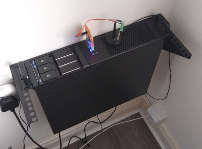
The first thing to consider was a case. My ADSL terminates in what I call the “comms room” - it has the electricity meter / distribution board and gas boiler, as well as being where one of the UniFi’s lives and where the downstairs ethernet terminates. In short it’s the right room for a server to live in. I don’t want a full rack, however, and ideally wanted something that could sit alongside the meter cabinet without protruding from the wall any further. A tower case would have worked, but only if turned sideways, which would have made it a bit awkward to access. I tried in vain to find a wall mount case with side access that was shallow enough, but failed. However in the process I discovered a 4U vertical wall mount. This was about the same depth as the meter cabinet, so an ideal choice. I paired it with a basic 2U case from X-Case, giving me a couple of spare U should I decide I want another rack-mount machine or two.
My old machine has 2 3.5” hotswap drive bays; this has been useful in the past when a drive failed even just to avoid having to take the machine apart. I still wanted to aim for low power consumption, so 2 drives is enough. I started with a pair of cheap 5.25” drive bay to dual 2.5” + 3.5” hotswap bay devices, but the rear SATA connectors ended up being very fragile and breaking off, so I bit the bullet and bought a SilverStone FS303. This takes up 2 5.25” bays and provides 3 x 3.5” hotswap bays. It’s well constructed and the extra bay has already turned out useful when a drive started to fail and I was able to put the replacement in and resync the RAID set before having to remove the old drive.
Now I had the externals sorted I needed to think about what to put inside. The only thing coming from the old machine were the hard disks (a 4T Seagate and a 6T WD RED, 4T of software RAID1 and 2T of unRAIDed backup space), so everything else was up for discussion. I toyed with an Intel i7-8700T - 6 cores in 35W. AMD have a stronger offering these days though and the AMD Ryzen 2700E with 8 cores in 45W seemed like a good option for an extra 10W. Plus on top there are several of the recent speculative execution exploits that don’t seem to affect AMD chips (or more recent Intel CPUs, but they weren’t out at the time in a low power format). Sadly the 2700E proved to be made of unobtanium; I sat with it on backorder for nearly 3 months before giving up and ordering a AMD Ryzen 2700 that was on offer. This is rated at up to 65W, but I considered trying to underclock if necessary or tweak the cpufreq settings at least.
Next up was a motherboard. The 2U case is short, but allows for MicroATX, an improvement over the MiniITX my last case needs. One of the things constraining me with the old machine was that it maxed out at 16G RAM, so I wanted something that would take more. It turns out there are a number of Socket AM4 MicroATX boards that will take 64G over 4 DIMMs. I chose an ASRock B450M Pro4, which had a couple of good reviews and seemed to have all the bits I wanted. It’s been decent so far - including having some interactions with ASRock support when I initially put an AMD 240GE (while waiting for the 2700E that was never coming) in it. I like to think of BIOS 3.10 as mine ;).
For RAM I went with a Corsair CMK32GX4M2A2400C14 Vengeance LPX 32GB (2 x 16GB) set. I’m sure I should care more about RAM but it was decently priced from a vendor I trust. At some point I’ll buy another set to bring the board up to the full 64GB, but for now this is twice what the old machine had.
Finally I decided to splash out on some SSD. The spinning rust is primarily for media (music + video shared out to Kodi etc) and backups, but I wanted to move my containers (home automation, UniFi controller, various others) over to SSD. I talked myself into a pair of Corsair MP510 960GB NVMe M.2 drives. One went on the motherboard slot and I had to buy a low profile PCIe adaptor for the other (of course they’re RAID1ed). They fly; initially I clocked them in at about 1.5GB/s until I realised the one in the add-in card was only using 2 PCIe lanes. Once I rejigged things so it had all 4 it can use I was up to 2.3GB/s. Impressive.
You’ll note I haven’t mentioned a graphic card here. I ended up with a cheap NVidia off eBay to get things going, but this is a server in a comms room and removing the graphics card saves me at least 10W of power (it was also the reason the NVMe drive only had 2 lanes). I couldn’t find an AM4 motherboard that did serial console, but the 450M Pro is happy to boot without a graphics card present, and I have GRUB onward configured to do serial console just in case.
And the power consumption? The previous machine idled at around 50W, getting to maybe 60-65W under load. I’ve cheated with the new machine; because the spinning rust is not generally in use it’s configured to spin down after 20 minutes idle. As a result the machine idles at around 36W. It hits 50W when the drives spin up, so for 8 cores compared to 2 we’re still sitting in the same ballpark. That’s good, because that’s the general case - idle here means Home Assistant operational, the UniFi controller going, the syslog container logging and so on. However the new server peaks considerably higher; if the drives are spun up and I compile a kernel I can hit 120W. However the compilation takes less than a quarter of the time - the machine is significantly faster than the old one, and even without taking advantage of the SSDs idles at roughly the same power level. I’d call that an overall win.
Burn it all
I am generally positive about my return to Northern Ireland, and decision to stay here. Things are much better than when I was growing up and there’s a lot more going on here these days. There’s an active tech scene and the quality of life is pretty decent. That said, this time of year is one that always dampens my optimism. TLDR: This post brings no joy. This is the darkest timeline.
First, we have the usual bonfire issues. I’m all for setting things on fire while having a drink, but when your bonfire is so big it leads to nearby flat residents being evacuated to a youth hostel for the night or you decide that adding 1800 tyres to your bonfire is a great idea, it’s time to question whether you’re celebrating your cultural identity while respecting those around you, or just a clampit (thanks, @Bolster). If you’re starting to displace people from their homes, or releasing lots of noxious fumes that are a risk to your health and that of your local community you need to take a hard look at the message you’re sending out.
Secondly, we have the House of Commons vote on Tuesday to amend the Northern Ireland (Executive Formation) Bill to require the government to bring forward legislation to legalise same-sex marriage and abortion in Northern Ireland. On the face of it this is a good thing; both are things the majority of the NI population want legalised and it’s an area of division between us and the rest of the UK (and, for that matter, Ireland). Dig deeper and it doesn’t tell a great story about the Northern Ireland Assembly. The bill is being brought in the first place because (at the time of writing) it’s been 907 days since Northern Ireland had a government. The current deadline for forming an executive is August 25th, or another election must be held. The bill extends this to October 21st, with an option to extend it further to January 13th. That’ll be 3 years since the assembly sat. That’s not what I voted for; I want my elected officials to actually do their jobs - I may not agree with all of their views, but it serves NI much more to have them turning up and making things happen than failing to do so. Especially during this time of uncertainty about borders and financial stability.
It’s also important to note that the amendments only kick in if an executive is not formed by October 21st - if there’s a functioning local government it’s expected to step in and enact the appropriate legislation to bring NI into compliance with its human rights obligations, as determined by the Supreme Court. It’s possible that this will provide some impetus to the DUP to re-form the assembly in NI. Equally it’s possible that it will make it less likely that Sinn Fein will rush to re-form it, as both amendments cover issues they have tried to resolve in the past.
Equally while I’m grateful to Stella Creasy and Conor McGinn for proposing these amendments, it’s a rare example of Westminster appearing to care about Northern Ireland at all. The ‘backstop’ has been bandied about as a political football, with more regard paid to how many points Tory leadership contenders can score off each other than what the real impact will be upon the people in Northern Ireland. It’s the most attention anyone has paid to us since the Good Friday Agreement, but it’s not exactly the right sort of attention.
I don’t know what the answer is. Since the GFA politics in Northern Ireland has mostly just got more polarised rather than us finding common ground. The most recent EU elections returned an Alliance MEP, Naomi Long, for the first time, which is perhaps some sign of a move to non-sectarian politics, but the real test would be what a new Assembly election would look like. I don’t hold out any hope that we’d get a different set of parties in power.
Still, I suppose at least it’s a public holiday today. Here’s hoping the pub is open for lunch.
Support your local Hackerspace
My first Hackerspace was Noisebridge. It was full of smart and interesting people and I never felt like I belonged, but I had just moved to San Francisco and it had interesting events, like 5MoF, and provided access to basic stuff I hadn’t moved with me, like a soldering iron. While I was never a heavy user of the space I very much appreciated its presence, and availability even to non-members. People were generally welcoming, it was a well stocked space and there was always something going on.
These days my local hackerspace is Farset Labs. I don’t have a need for tooling in the same way, being lucky enough to have space at home and access to all the things I didn’t move to the US, but it’s still a space full of smart and interesting people that has interesting events. And mostly that’s how I make use of the space - I attend events there. It’s one of many venues in Belfast that are part of the regular Meetup scene, and for a while I was just another meetup attendee. A couple of things changed the way I looked at. Firstly, for whatever reason, I have more of a sense of belonging. It could be because the tech scene in Belfast is small enough that you’ll bump into the same people at wildly different events, but I think that’s true of the tech scene in most places. Secondly, I had the realisation (and this is obvious once you say it, but still) that Farset was the only non-commercial venue that was hosting these events. It’s predominantly funded by members fees; it’s not getting Invest NI or government subsidies (though I believe Weavers Court is a pretty supportive landlord).
So I became a member. It then took me several months after signing up to actually be in the space again, but I feel it’s the right thing to do; without the support of their local tech communities hackerspaces can’t thrive. I’m probably in Farset at most once a month, but I’d miss it if it wasn’t there. Plus I don’t want to see such a valuable resource disappear from the Belfast scene.
And that would be my message to you, dear reader. Support your local hackerspace. Become a member if you can afford it, donate what you can if not, or just show up and help out - as non-commercial entities things generally happen as a result of people turning up and volunteering their time to help out.
(This post prompted by a bunch of Small Charity Week tweets last week singing the praises of Farset, alongside the announcement today that Farset Labs is expanding - if you use the space and have been considering becoming a member or even just donating, now is the time to do it.)
NIDevConf 19 slides on Home Automation
The 3rd Northern Ireland Developer Conference was held yesterday, once again in Riddel Hall at QUB. It’s a good venue for a great conference and as usual it was a thoroughly enjoyable day, with talks from the usual NI suspects as well as some people who were new to me. I finally submitted a talk this year, and ended up speaking about my home automation setup - basically stringing together a bunch of the information I’ve blogged about here over the past year or so. It seemed to go well other than having a bit too much content for the allocated time, but I got the main arc covered and mostly just had to skim through the additional information. I’ve had a similar talk accepted for DebConf19 this Summer, with a longer time slot that will allow me to go into a bit more detail about how Debian has enable each of the pieces.
Slides from yesterday’s presentation are below; if you’re a regular reader I doubt there’ll be anything new and it’s a slide deck very much intended to be talked around rather than stand alone so if you weren’t there they’re probably not that useful. There’s a recording of the talk which I don’t hate as much as I thought I would (and the rest of the conference is also on the NIDevConf Youtube channel).
Note that a lot of the slides have very small links at the bottom which will take you to either a blog post expanding on the details, or an external reference I think is useful.
Also available for direct download.
More Yak Shaving: Moving to nftables to secure Home Assistant
When I setup Home Assistant last year one of my niggles was that it wanted an entire subdomain, rather than being able to live under a subdirectory. I had a desire to stick various things behind a single SSL host on my home network (my UniFi controller is the other main one), rather than having to mess about with either SSL proxies in every container running a service, or a bunch of separate host names (in particular one for the backend and one for the SSL certificate, for each service) in order to proxy in a single host.
I’ve recently done some reorganisation of my network, including building a new house server (which I’ll get round to posting about eventually) and decided to rethink the whole SSL access thing. As a starting point I had:
- Services living in their own containers
- Another container already running Apache, with SSL enabled + a valid external Let’s Encrypt certificate
And I wanted:
- SSL access to various services on the local network
- Not to have to run multiple copies of Apache (or any other TLS proxy)
- Valid SSL certs that would validate correctly on browsers without kludges
- Not to have to have things like
hass-hostas the front end name andhass-backend-hostas the actual container name.
It dawned on me that all access to the services was already being directed through the server itself, so there was a natural redirection point. I hatched a plan to do a port level redirect there, sending all HTTPS traffic to the service containers to the container running Apache. It would then be possible to limit access to the services (e.g. port 8123 for Home Assistant) to the Apache host, tightening up access, and the actual SSL certificate would have the service name in it.
First step was to figure out how to do the appropriate redirection. I was reasonably sure this would involve some sort of DNAT in iptables, but I couldn’t find a clear indication that it was possible (there was a lot of discussion about how you also ended up needing SNAT, and I needed multiple redirections to 443 on the Apache container, so that wasn’t going to fly). Having now solved the problem I think iptables could have done it just fine, but I ended up being steered down the nftables route. This is long overdue; it’s been available since Linux 3.13 but lacking a good reason to move beyond iptables I hadn’t yet done so (in the same way I clung to ipfwadm and ipchains until I had to move).
There’s a neat tool, iptables-restore-translate, which can take the output of iptables-save and provide a simple translation to nftables. That was a good start, but what was neater was moving to the inet filter instead of ip which then mean I could write one set of rules which applied to both IPv4 and IPv6 services. No need for rule duplication! The ability to write a single configuration file was nicer than the sh script I had to configure iptables as well. I expect to be able to write a cleaner set of rules as I learn more, and although it’s not relevant for the traffic levels I’m shifting I understand the rule parsing is generally more efficient if written properly.Finally there’s an nftables systemd service in Debian, so systemctl enable nftables turned on processing of /etc/nftables.conf on restart rather than futzing with a pre-up in /etc/network/interfaces.
With all the existing config moved over the actual redirection was easy. I added the following block to the end of nftables.conf (I had no NAT previously in place), which redirects HTTPS traffic directed at 192.168.2.3 towards 192.168.2.2 instead.
nftables dnat configuration
table ip nat {
        chain prerouting {
                type nat hook prerouting priority 0
                # Redirect incoming HTTPS to Home Assistant to Apache proxy
                iif "enp24s0" ip daddr 192.168.2.3 tcp dport https \
                        dnat 192.168.2.2
        }
        chain postrouting {
                type nat hook postrouting priority 100
        }
}
I think the key here is I can guarantee that any traffic coming back from the Apache proxy is going to pass through the host doing the DNAT; each container has a point-to-point link configured rather than living on a network bridge. If there was a possibility traffic from the proxy could go direct to the requesting host (e.g. they were on a shared LAN) then you’d need to do SNAT as well so the proxy would return the traffic to the NAT host which would then redirect to the requesting host.
Apache was then configured as a reverse proxy, with my actual config ending up as follows. For now I’ve restricted access to within my house; I’m still weighing up the pros and cons of exposing access externally without the need for a tunnel. The domain I used on my internal network is a proper registered thing, so although I don’t expose any IP addresses externally I’m able to use Mythic Beasts’ DNS validation instructions and have a valid cert.
Apache proxy config for Home Assistant
<VirtualHost *:443>
        ServerName hass-host

        ProxyPreserveHost On
        ProxyRequests off
        RewriteEngine on

        # Anything under /local/ we serve, otherwise proxy to Home Assistant
        RewriteCond %{REQUEST_URI} '/local/.*'
        RewriteRule .* - [L]
        RewriteCond %{HTTP:Upgrade} =websocket [NC]
        RewriteRule /(.*) ws://hass-host:8123/$1 [P,L]
        ProxyPassReverse /api/websocket ws://hass-host:8123/api/websocket
        RewriteCond %{HTTP:Upgrade} !=websocket [NC]
        RewriteRule /(.*) http://hass-host:8123/$1 [P,L]
        ProxyPassReverse / http://hass-host:8123/

        SSLEngine on
        SSLCertificateFile /etc/ssl/le.crt
        SSLCertificateKeyFile /etc/ssl/private/le.key
        SSLCertificateChainFile /etc/ssl/lets-encrypt-x3-cross-signed.crt

        # Static files can be hosted here instead of via Home Assistant
        Alias /local/ /srv/www/hass-host/
        <Directory /srv/www/hass-host/>
                Options -Indexes
        </Directory>

        # Only allow access from inside the house
        ErrorDocument 403 "Not for you."
        <Location />
                Order Deny,Allow
                Deny from all
                Allow from 192.168.1.0/24
        </Location>
</VirtualHost>
I’ve done the same for my UniFi controller; the DNAT works exactly the same, while the Apache reverse proxy config is slightly different - a change in some of the paths and config to ignore the fact there’s no valid SSL cert on the controller interface.
Apache proxy config for Unifi Controller
<VirtualHost *:443>
	ServerName unifi-host

	ProxyPreserveHost On
	ProxyRequests off

	SSLProxyEngine on
	SSLProxyVerify off
	SSLProxyCheckPeerCN off
	SSLProxyCheckPeerName off
	SSLProxyCheckPeerExpire off

	AllowEncodedSlashes NoDecode
	ProxyPass /wss/ wss://unifi-host:8443/wss/
	ProxyPassReverse /wss/ wss://unifi-host:8443/wss/
	ProxyPass / https://unifi-host:8443/
	ProxyPassReverse / https://unifi-host:8443/

	SSLEngine on
	SSLCertificateFile /etc/ssl/le.crt
	SSLCertificateKeyFile /etc/ssl/private/le.key
	SSLCertificateChainFile /etc/ssl/lets-encrypt-x3-cross-signed.crt

	# Only allow access from inside the house
	ErrorDocument 403 "Not for you."
	<Location />
		Order Deny,Allow
		Deny from all
		Allow from 192.168.1.0/24
	</Location>
</VirtualHost>
(worth pointing out that one of my other Home Assistant niggles has also been fixed - there’s now the ability to setup multiple users and separate out API access to OAuth, rather than a single password providing full access. It still needs more work in terms of ACLs for users, but that’s a bigger piece of work.)
subscribe via RSS