Controlling the Energenie 433MHz mains switch with an ATTiny
My first attempt at home automation involved a dark internal staircase in my flat, a set of white LED fairy lights and a plan to make them switch on when I was at home and the sun had set. I purchased a set of Energenie sockets and the associated Pi-Mote to control the lights and looked at what my control options were. Nothing really stood out so I started writing some Python that would watch for my phone being connected to the wifi, look at whether the sun had set and send the appropriate commands. Unfortunately the range on the Energenie sockets and/or the Pi-mote ended up too poor to work from where the Pi was located to the socket out in the hallway. I tried soldered an antenna onto the Pi-mote, but it still ended up too unreliable. Subsequently something happened to the Pi-mote and it stopped working entirely. The sockets were still working ok, and for a while I made some use of them with the provided remote control, but until recently they had been sitting in a box for a couple of years.
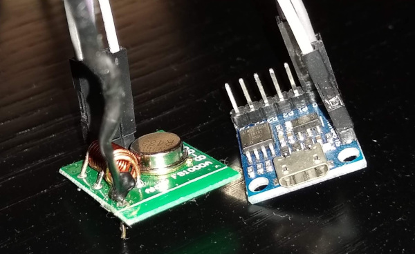
With my more recent, more successful foray into automation I decided to try and revive the Energenie sockets as part of my setup. Poking the Pi-mote confirmed it was dead - trying to drive it manually rather than with the Pi resulted in no output signal. However I’d purchased a cheap 433MHz receiver/transmitter pair (MX-RM-5V + FS1000A) - very cheap and nasty, but easy to poke. I found a good writeup of the Energenie protocol and how to drive it via FT232R bitbanging and Glen Pitt-Pladdy also had some details. Using PulseView and my cheap Cypress FX2 analyser hooked up to the MX-RM-5V I was able to capture the 20 digit code from my remote control.
All that remained was to try and transmit the code + appropriate power on/off commands for each of my 4 sockets. I still have spare Digispark clones, so that seemed like a good starting point. My initial first steps with ATTinys involved a relay board which was available with up to 8 ports. It made sense to try and emulate a 4 port relay board on a device that would actually send out the appropriate 433MHz signals. In addition the relay boards have 5 digits of configurable serial number - perfect for a 20 bit ID code! I took my existing code and fixed it up so that instead of setting/clearing the appropriate output pin bit it wiggled a single pin, connected to the FS1000A, in the appropriate manner for the Energenie. It took a little bit of twiddling, and I had to solder an antenna onto the FS1000A to get better range, but I’ve ended up with 2 sockets in the same room as the Digispark/transmitter dongle, and another in the next room on just the other side of the wall.
For initial testing I used Darryl Bond’s usbrelay, which is handy because it also supports setting the serial number, so I didn’t have to hard code anything into my image. Ultimately I wrote my own code to control the device in Python, and of course hooked it into my MQTT setup. This tied it into Home Assistant like any other set of MQTT lights, and ultimately into Alexa.
Ultimately the SonOff is better technically - the use of an ESP8266 directly on the device means you get a direct secure MQTT/TLS connection rather than an easily sniffable/clonable 433MHz signal, plus it’s bidirectional so you can be sure the device is in the state you think it is. However I had these switches lying around and a spare Digispark so the only expenditure was a couple of quid for the transmitter/receiver pair. Plus it was fun to figure it out and end up with a useful result, and some of the information learned will be useful for controlling my heating (which is on a 433MHz thermostat).
The code is locally and on GitHub in case it’s of use/interest to anyone else.