Maxcio W-UK007S Power Monitoring Smart Plug notes
The house server I built in 2013 is getting on a bit, so I’d like to replace it. That’s currently held up on availability of Ryzen 7 2700E CPUs, which look to be the best power consumption/performance trade-off available at present. While I wait for stock I figured I should see how the current i3-3220T is doing.
To do so I decided to buy a Smart Plug that advertised energy monitoring, planning to integrate it into my current setup for the monitoring and then being able to use it for general power control once the upgrade comparison is complete. I ended up with a pair of Maxcio Smart Plugs - pricing and availability worked out and I’d found confirmation that the W-US002S was ESP8266 based.
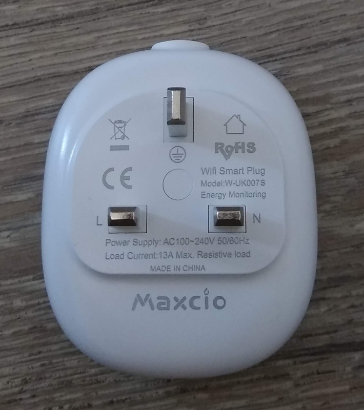
The model I ended up with is externally marked as a W-UK007S. It’s a fairly neat form factor (slightly smaller than the SonOff S26 I already have, which doesn’t do power monitoring). It also turned out to be easy to take apart; there is a circular cover in the middle which can be carefully popped out, revealing the single screw holding the device together.
The back plate has 4 clips holding it together at the corners and can be gently pried off. Inside there’s a main circuit board labelled “W-US0007S-V0.3” which has the relay on it and a perpendicular board with the ESP8266 module and power monitoring chip on it.
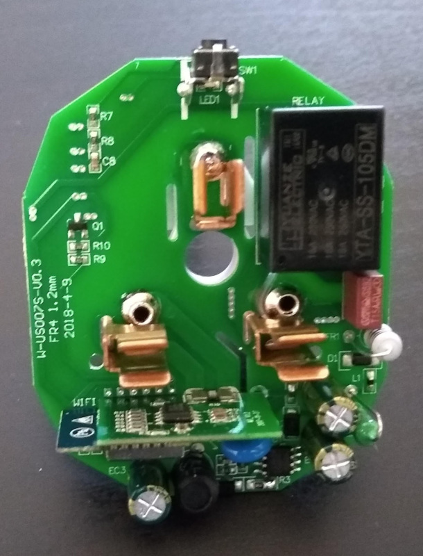
Sadly the layout didn’t match anything I was familiar with, or could find any details of. That meant I had to do some detective work to figure out how to talk to the ESP8266. It was easy enough to work out GND + VCC by following PCB tracks. Likewise the relay, the button and the LED (underneath the button, and separately controlled from the relay, unlike the S26). Next move was to hook up power (just a low voltage supply to GND/VCC, I did not engage in any experimentation involving mains voltages!) and monitor each unknown pin in turn in the hope I’d find TX (even if the supplied firmware didn’t print anything out the ESP8266 prints a message on boot, so I’d definitely see something if it was there).
Thankfully TX was brought out to the module connection to the main PCB, so I had something I could monitor.
Maxcio boot log
 ets Jan  8 2013,rst cause:1, boot mode:(3,7)

load 0x40100000, len 1396, room 16
tail 4
chksum 0x89
load 0x3ffe8000, len 776, room 4
tail 4
chksum 0xe8
load 0x3ffe8308, len 540, room 4
tail 8
chksum 0xc0
csum 0xc0

2nd boot version : 1.4(b1)
  SPI Speed      : 40MHz
  SPI Mode       : QIO
  SPI Flash Size & Map: 8Mbit(512KB+512KB)
jump to run user1 @ 1000

OS SDK ver: 1.4.2(23fbe10) compiled @ Sep 22 2016 13:09:03
phy v[notice]user_main.c:268 SDK version:1.4.2(23fbe10)
[notice]user_main.c:270 tuya sdk version:1.0.6
[notice]user_main.c:275 tuya sdk compiled at Jul 26 2017 15:27:36
[notice]user_main.c:277 BV:5.20 PV:2.1 LPV:3.1
reset reason: 0
epc1=0x00000000, epc2=0x00000000, epc3=0x00000000, excvaddr=0x00000000,depc=0x00000000
mode : softAP(de:4f:22:2c:76:93)
dhcp server start:(ip:192.168.4.1,mask:255.255.255.0,gw:192.168.4.1)
add if1
bcn 100
bcn 0
del if1
usl
mode : sta(dc:4f:22:2c:76:93)
add if0
scandone

[notice]device.c:1694 fireware info name:esp_hys_qx_single_light_jlplug version:1.0.0
[notice]device.c:1695 PID=gDYvLrWhRoqpgHMj

[notice]device.c:1696 FW Compiled date:Feb  5 2018
[notice]gw_intf.c:240 Authorization success
[notice]device.c:1722 ##  AUTH DONE ##

[err]bl0937.c:1013 ### get_coefficient get err: 28
[err]device.c:1767 get ele data err...
[err]device.c:1772 get tem ele data err...
del if0
usl
mode : null
force slp enable,type: 2
fpm open,type:2 0
[notice]device.c:2041  # STAT_STA_UNCONN STAT_LOW_POWER#

[notice]device.c:2042  # STAT_STA_CONN #

[notice]device.c:648 #####I_VAL:0#####

[notice]device.c:654 ***************************Check Start 1**********************************
[notice]device.c:655 ### cur:0 mA power:0 W vol:0 V
[notice]device.c:656 ****************************Check Stop**********************************
Next I took the remaining unknown pins and tried grounding them on boot, in an attempt to find GPIO0 (which needs to be grounded to access the ROM serial bootloader). I ended up finding GPIO2 first, and then eventually figuring out the LED was using GPIO0 - learning the lesson not to assume pins don’t have multiple uses. Now I had TX + GPIO0 I could hold GPIO0 on boot and look for RX by probing the remaining pins and seeing if esptool could talk to the bootloader. Again, I was successful.
At that point I was able to download the firmware from flash, and poke it in the hope of working out the GPIO assignments (I’m a software guy, I’m happier with an assembly dump than probing randomly around a board in the hope of enlightenment). I generated a crude .elf from the flash dump using esp-bin2elf, hacking it up to cope better with an OTA ROM image and skip the boot loader. I initially used objdump to examine the result, which wasn’t that helpful, and then found ScratchABit, which made things much easier. What would have been ideal is some way to load in the .a static libraries from the SDK and automatically map those to the code; as well as providing some useful symbols it would have avoided work looking at functions that were irrelevant. The ESP8266 seems to want various levels of indirection to access functions and memory locations so it’s not just a simple matter of looking for an I/O request to a specific location, but I was able to figure out that the button was on GPIO13 and the relay on GPIO15.
All that left was the bit I was actually interested in - the power monitoring. The appropriate chip (clearly attached to a low resistance bridge from one of the AC power pins, and also attached to the other pin) on the PCB was marked “HJL-01 / J1749CYH / D797480E”. Whatever you find on the web this is not the same as the HLW8012. It’s very similar in operation but is actually a BL0937. Electrodragon’s Energy Meter page was the best resource I found - it has a link to the Chinese datasheet for the BL0937, which in combination with Google Translate allows the basic principles to be understood. Both devices work by having a pin (CF) which outputs pulses based on monitored power consumption, and a pin (CF1) which can be switched between monitoring current and voltage via a third pin (SEL). For the BL0937 you can just count pulses; the pulse width is fixed at 38µS and it’s just the frequency which varies. I’d found the GPIO interupt handler in my flash disassembly which indicated that GPIO5 was connected to CF and GPIO14 to CF1. Additionally the handler around GPIO14 needs to check which mode the chip is currently in, which let me discover GPIO12 was connected to this pin.
That resulted in the following pin mapping of the daughter PCB; the remaining 4 pins weren’t of interest once I had the ones I needed, so I didn’t do further investigation:
PCB EDGE

                +----+
LED    / GPIO0  |1 12| 3.3V
                |2 11|
BUTTON / GPIO13 |3 10| GPIO2
TX              |4  9| RX
RELAY  / GPIO15 |5  8|
GND             |6  7|
                +----+

PCB CENTER
Of course the frequency values that come out of the BL0937 are not directly usable; there’s a certain amount of conversion/calibration that needs to be done. Thankfully although the datasheet has an equation that includes an odd constant value as well as the internal reference voltage this all boils down to a simple scaling value. I ended up using a multimeter to calibrate the voltage and then a standalone power meter + table lamp to calibrate power/current. Better results could be obtained with a constant voltage source and a known resistance load but this worked out close enough for my needs.
I wrote my own driver to fit within the ESP8266 MQTT framework I use, but if you’re looking for something more off the shelf ESPurna is probably a good start. Ticket #737 talks about adding support for the BL0937 (it’s close enough to the HLW8012 that you can get away with just changing the scaling factors), and the Homecube SP1 seems to use the same GPIOs for the various pieces of hardware.
I’ve put all the images from my teardown into a W-UK007S Teardown Album on Google Photos, in case it’s useful to anyone.