Go Baby Go
I’m starting a new job next month and their language of choice is Go. Which means I have a good reason to finally get around to learning it (far too many years after I saw Marga talk about it at DebConf). For that I find I need a project - it’s hard to find the time to just do programming exercises, whereas if I’m working towards something it’s a bit easier. Naturally I decided to do something home automation related. In particular I bought a couple of Xiaomi Mijia Temperature/Humidity sensors a while back which also report via Bluetooth. I had a set of shell scripts polling them every so often to get the details, but it turns out they broadcast the current status every 2 seconds. Passively listening for that is a better method as it reduces power consumption on the device - no need for a 2 way handshake like with a manual poll. So, the project: passively listen for BLE advertisements, make sure they’re from the Xiaomi device and publish them via MQTT every minute.
One thing that puts me off new languages is when they have a fast moving implementation - telling me I just need to fetch the latest nightly to get all the features I’m looking for is a sure fire way to make me hold off trying something. Go is well beyond that stage, so I grabbed the 1.11 package from Debian buster. That’s only one release behind current, so I felt reasonably confident I was using a good enough variant. For MQTT the obvious choice was the Eclipse Paho MQTT client. Bluetooth was a bit trickier - there were more options than I expected (including one by Paypal), but I settled on go-ble (sadly now in archived mode), primarily because it was the first one where I could easily figure out how to passively scan without needing to hack up any of the library code.
With all those pieces it was fairly easy to throw together something that does the required steps in about 200 lines of code. That seems comparable to what I think it would have taken in Python, and to a large extent the process felt a lot closer to writing something in Python than in C.
Now, this wasn’t a big task in any way, but it was a real problem I wanted to solve and it brought together various pieces that helped provide me with an introduction to Go. I’ve a lot more to learn, but I figure I should write up my initial takeaways. There’s no mention of goroutines or channels or things like that - I’m aware of them, but I haven’t yet had a reason to use them so don’t have an informed opinion at this point.
I should point out I read Rob Pike’s Go at Google talk first, which helped understand the mindset behind Go a lot - it’s not trying to solve the same problem as Rust, for example, but very much tailored towards a set of the problems that Google see with large scale software development. Also I’m primarily coming from a background in C and C++ with a bit of Perl and Python thrown in.
The Ecosystem is richer than I expected
I was surprised at the variety of Bluetooth libraries available to me. For a while I wasn’t sure I was going to find one that could do what I needed without hackery, but most of the Python BLE modules have the same problem.
Static binaries are convenient
Go builds a mostly static binary - my tool only links against various libraries from libc, with the Bluetooth and MQTT Go modules statically linked into the executable file. With my distro minded head on I object to this; it means I need a complete rebuild in case of any modification to the underlying modules. However the machine I’m running the tool on is different than the machine I developed on and there’s no doubt that being able to copy a single binary over rather than having to worry about all the supporting bits as well is a real time saver.
The binaries are huge
This is the flip side of static binaries, I guess. My tool is a 7.6MB binary file. That’s not a problem on my AMD64 server, but even though Go seems to have Linux/MIPS support I doubt I’ll be running things built using it on my OpenWRT router. Memory usage seems sane enough, but that size of file is a significant chunk of the available flash storage for small devices.
Module versioning isn’t as horrible as I expected
A few years back I attended a Go talk locally and asked a question about module versioning and the fact that by default modules were pulled directly from Git repositories, seemingly without any form of versioning. The speaker admitted that their example code had in fact failed to compile the previous day because of a change upstream that changed an API. These days things seem better; I was pointed at go mod and in particular setting GO111MODULE=on for my 1.11 compiler, and when I first built my code Go created a go.mod with a set of versioned dependencies. I’m still wary of build systems that automatically grab code from the internet, and the pinning of versions conflicts with an ability to be able to automatically rebuild and pick up module security fixes, but at least there seems to be some thought going into this these days.
I love maps
Really this is more a generic thing I miss when I write C. Perl hashes, Python dicts, Go maps. An ability to easily stash things by arbitrary reference without having to worry about reallocation of the holding structure. I haven’t delved into other features Go has over C particularly yet so I’m sure there’s more to take advantage of, but maps are a good start.
The syntax is easy enough
The syntax for Go felt comfortable enough to me. I had to look a few bits and pieces up, but nothing grated. go fmt is a nice touch; I like the fact that modern languages are starting to have a well defined preferred style. It’s a long time since I wrote any Pascal, but as a C programmer things made sense.
I’m still not convinced about garbage collection
One of the issues I hit while developing my tool was that it would sit and spin and take more and more memory. This turned out to be a combination of some flaky Bluetooth hardware returning odd responses, and my failure to handle the returned error message. Ultimately this resulted in a resource leak causing the growing memory use. This would still have been possible without garbage collection, but I think not having to think about memory allocation/deallocation made me more complacent. Relying on the garbage collector to free up resources means you have to be sure nothing is holding a reference any more (even if it won’t use it). I think it will take further time with Go development to fully make my mind up, but for now I’m still wary.
Code, in the unlikely event it’s helpful to anyone, is on GitHub.
Setting up SSH 2FA using TOTP
I spend a lot of time connected to remote hosts. My email and IRC client live on a dedicated server with Bytemark, which makes it easy to access wherever I am in the world. I have a well connected VM for running Debian package builds on using sbuild. At home my Home Assistant setup lives in its own container. And of course that lives on a server which is in the comms room and doesn’t even have a video card installed. At work my test machines are all in the server room rather than noisily on my desk. I connect to all of these with SSH (and screen, though I keep meaning to investigate tmux more thoroughly) - I’ve been doing so since the days of dialup, I’m very happy with the command line and I generally don’t need the overhead of a remote GUI. I don’t think I’m unusual in this respect (especially among people likely to be reading this post).
One of the things I love about SSH is the ability to use SSH keys. That means I don’t have to remember passwords for hosts - they go in my password manager for emergencies, I login with them once to drop my .ssh/authorised_keys file in place, and I forget them. For my own machines, where possible, I disable password logins entirely. However there are some hosts I want to be able to get to even without having an SSH key available, but equally would like a bit more security on. A while back I had a conversation with some local folk about the various options and decided that some sort of two-factor authentication (2FA) was an appropriate compromise; I was happy to trust an SSH key on its own, but for a password based login I wanted an extra piece of verification. I ended up putting the Google Authenticator on my phone, which despite the name is actually a generic implementation of the TOTP and HTOP one-time password algorithms. It’s turned out useful for various websites as well (in particular at work I have no phone coverage and 2FA on O365. Having Authenticator installed makes that easier than having to wave my phone near the window to get an SMS login token).
For the server side I installed the Google Authenticator PAM module, conveniently available in Debian with a simple apt install libpam-google-authenticator. I added:
auth required pam_google_authenticator.so nullok
to /etc/pam.d/sshd below the @include common-auth line, and changed
ChallengeResponseAuthentication no
in /etc/ssh/sshd_config to be yes instead. servicectl restart sshd restarts SSH and brings the new config into play. At this point password only logins are still ok (thanks to the nullok above). To enable 2FA you then run google-authenticator as your normal user. This asks a bunch of questions - I went for TOTP (i.e. time based), disabled multiple uses and turned on the rate-limiting. The tool will display an ASCII art QR code (make sure your terminal window is big enough) that can be scanned by the phone app. From this point on the account will require an authentication code after a successful password entry, but also allow SSH key only logins.
For the avoidance of doubt, this does not involve sending any information off to Google or any other network provider. TOTP/HOTP are self contained protocols, and it’s the scanning of the QR code/entering the secret key at setup time that binds the app to the server details. There are other app implementations which will work just fine.
(This post mostly serves to document the setup steps for my own reference; I set it up originally over a year ago and have just had to do so again for a new machine.)
Making my first PCB
I’ve written a lot about my various home automation bits, but I haven’t generally posted pictures. That’s because my construction skills aren’t great; I’m wiring together modules and that tends to make it harder to case things properly and make them look nice. My first attempt to be better about this was to buy a prototyping box which had a case + board paired with it I could attach modules to. This helped a bit, but still involved a mess set of wiring to attach things together (proper strip board would have been more useful than just copper pads).
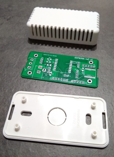
I then started to notice I was getting JLCPCB ads while web browsing, offering 10 PCBs for $2. That seemed like a good deal, and I thought if I did things right I could find the right case and then make sure the PCB fitted in it. I found a small vented white case available from CPC. This allows me to put a temperature sensor inside for some devices. KiCad seemed like a good option for trying to design my basic schematic and lay it out, so I installed it and set to work trying to figure out what I wanted to put on the board, and how to actually drive KiCad.
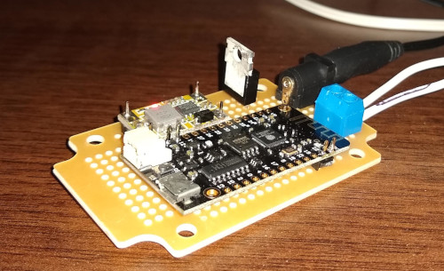
As the core I chose an ESP-07 ESP8266 module. I’ve used a few of them before and they’re cheap and convenient. I added an LDO voltage regulator (LD1117) so I could use a 5V PSU (and I’m hoping with a heatsink I can get away with a 12V supply as well, even if it’s more inefficient). That gave enough to get a basic schematic once I’d added the necessary pull-up/down resistors for the ESP8266 and decoupling capacitors. I included a DC barrel jack for the PSU, and pin headers for the serial port, SPI pins and GPIO0 for boot selection. One of my use cases is to make an LED strip controller, so I threw in a screw terminal block for power + control - the board is laid out to allow a MOSFET for a simple white 12V LED strip, or the same GPIO taken straight to the terminal block for controlling a WS2812 strip. By including a couple of extra pull-up resistors I added the option of I2C for further expansion.
After I had the basic schematic I moved to layout. Luckily Hammond provide 2D CAD files for the case, so I figured I would import them into KiCad’s PCB layout tool to make sure things would fit. That took a little bit of effort to go from DWG to DXF and trim it down (I found a web tool to do the initial conversion and then had to strip out the bits of the case that weren’t related to the PCB size + mounting points). I wasn’t confident enough that the edge cuts layer would include the mounting holes, so I manually placed some from KiCad over the right spots.
At this point I was glad I had a simple design, because it took me a while to decide how to place things and then route the tracks. I ended up altering some header pin assignments from the original design to make things a bit easier to route, and took advantage of the double sided board to put some components underneath, to ease both routing and space constraints. Originally I had planned to make things easy and go for through-hole components (I’ve never SMD soldered before) but in the interests of making use of space I risked the “1206 Handsoldered” footprint option in KiCad, which seems to be like the Duplo of SMD components. I kept my regulator as through-hole to make a larger heatsink easier. I also discovered I had a bit of spare space, so I put down a footprint and pin headers for a PCF8574 I2C GPIO expander to allow for more IO if I needed it. Finally the I2C pin header was laid out to allow a BME280 module to be soldered directly on top, allowing for easy addition of environmental monitoring without having to solder ridiculously small devices myself.
Once I had all of that done I printed out my final design, carefully cut around the edge and made sure it fitted into the case and the components I already had where the right size. Once I was fairly confident I’d checked as much as I could I then did a Gerber export and uploaded to JLCPCB. The process was very smooth - you upload a zip file, can do a sanity check viewing of how they’ve parsed it, select various options for the PCB (I left almost everything as the default) and then submit the order. Over the next couple of days you can see things progress through the various manufacturing stages and then get dispatched. For the first order it turns out you get free DHL Express delivery, so I ordered on Friday morning and had 10 boards by Wednesday afternoon. All for £1.58. A friend tells me subsequent orders have standard China Post shipping as standard, but for that price it’s still hard to beat!
How did they turn out? Pretty well. The quality of the boards is excellent to my untrained eye. Soldering the SMD bits got easier when I switched to a better bit on my soldering iron and made sure it was well screwed in (otherwise it, er, doesn’t heat up particularly reliably) - my soldering is still terrible, but it gets the job done. Most importantly the PCB fit the case footprint perfectly - mounting holes in the right place, edge cuts the right shape/size. A couple of snips to the vents and the barrel jack connector and terminal block are easily accessible, and it still looks fairly neat. The main mistake I made was not thinking about component heights! In particular the barrel jack was a couple of mm too high, which a quick shave with a Dremel sorted. The voltage regulator also stood far too high, which I fixed by bending at a 90° angle over the board. This will limit my options for a heatsink, but for 5V power this isn’t necessary anyway.
So far I’ve assembled 2 boards, both controlling WS2812 LED strips and powered by 5V PSUs. One also has a BME280 added. I’m waiting on more parts arriving and then will try out a 12V / white LED strip combo. I’m really pleased with the overall results; it took a while playing with KiCad to get to the point I was confident to send my files off to be manufactured (the print outs helped a lot), and failing to think about component heights was a silly mistake, but having everything mounted on a single PCB and firmly screwed into a case makes for a much more robust project. The first 2 are both hidden out of the way, but it’s reassuring to know they’re not particularly fragile like some of my earlier constructions. And I’m already trying to work out what PCB I want to make next…
Bordering on ridiculous
There’s been a lot of discussion (to put it mildly) about the backstop in regards to Brexit. Effectively the TL;DR is that it’s designed to prevent the return of a hard border between Northern Ireland and Ireland, in the absence of some more organized solution. As someone born and raised in Northern Ireland I’m in favour of that. My parents live in Newry, which is just north of the border on the main Belfast/Dublin road. I remember the border checkpoint.
The backstop causes problems because it requires the United Kingdom to keep in sync with the EU in many respects, to retain the customs union and allow the free movement of goods across the border in a friction-free manner. Originally there was a suggestion that this union could apply solely to Northern Ireland, with some sort of checks made on the air/sea border between NI and the rest of the UK. The DUP rejected any suggestion of a border in the Irish Sea, and as the party propping up the Tories they have some sway in this whole thing. That’s unfortunate, as I think that this sort of special status for Northern Ireland could make it a very attractive place to do business, with good access to both the rest of the UK and the EU. The DUP claim to be rejecting anything that might make Northern Ireland separate from the UK. What they fail to acknowledge is the multitude of ways in which NI is separate, some of them their doing.
Let’s start with some legal examples. Belfast was the first place to have generally available civil partnerships for gay couples (there was an earlier exceptional ceremony in Brighton for a terminally ill man). Today Northern Ireland is the only place not to allow same sex marriage - England and Wales introduced the Marriage (Same Sex Couples) Act 2013 and Scotland introduced the Marriage and Civil Partnership (Scotland) Act 2014. The DUP have repeatedly used the Petition of Concern to block such legislation in Northern Ireland, and stated they will continue to do so.
The other headline difference is the fact that the Abortion Act 1967 does not apply in Northern Ireland, which instead falls back to the Criminal Justice Act (Northern Ireland) 1945 and the older Offences Against the Person Act 1861, only allowing abortion in cases where it is to preserve the life of the mother.
Less of a headline difference is the fact it’s illegal to give a child under 16 alcohol in Northern Ireland (Children and Young Persons Act (Northern Ireland) 1968 s.25), unless it’s on the order of a doctor. Everywhere else it’s illegal for under 5s (Children and Young Persons Act 1933 s.5), but ok for older children in private premises. It’s wise to try to prevent underage drinking, but I’d have thought enabling it legally in the home isn’t the risk factor we should be worried about here. NI also has more restrictive off-license alcohol licensing, leading to weird cordoned off areas in supermarkets where they keep the alcohol and most small shops not stocking it at all.
All of these legal differences are reconcilable with the DUP’s status as a conservative Christian right party. However they all serve to separate Northern Ireland more from the rest of the UK, making it look like a parochial backwater, and that’s harder to reconcile with the DUP’s statement that they want to avoid that. Equally there are other pieces of legislation that have variations in the Northern Ireland implementation (and the fact there’s even a separate Act or Order for NI for things predating devolution is sometimes an oddity).
For example, The Employment Rights (Northern Ireland) Order 1996, Article 140 specifies that an employee needs 1 year continuous employment to be able to make an unfair dismissal claim, while the Employment Rights Act 1996, s.108 requires 2 years before such a claim can be made in the rest of the UK. Good for workers in NI, but not a logical difference to have.
We can’t even claim these differences all pre-date the Good Friday Agreement Stormont Assembly. In 2014 the DUP were quite happy to try and diverge NI’s tax regime from the rest of the UK by aiming for a corporation tax reduction that was, irony of ironies, designed to bring NI into line with the rest of Ireland in an attempt to get some of the inward investment pie.
It’s also worth noting that land law is significantly different between NI and England & Wales (to the extent that while doing my law degree I was taught them as 2 parallel strands rather than the lecturers simply pointing out the divergences along the way). Scotland is even more different, so that’s perhaps not as useful an example of variation, but it does usefully lead into a discussion about differences in the provision of government services. Searching the Land Registry for Northern Ireland is in-person physical act. Doing so for England and Wales with the HM Land Registry is possible online.
This can be seen again in the area of driving licences, something you’d expect a unified UK approach for. The rest of the UK has abolished the paper counterpart for driving licences. Not Northern Ireland. If you hold an NI licence and want to hire a car don’t forget to bring your paper part! (Yes, this has bitten me once.) Northern Ireland was also the first part of the UK to have a photograph as part of the driving licence (probably because we were the only part of the UK being stopped at army checkpoints and asked for ID).
On the subject of cars, the MOT in Northern Ireland is performed in government run test centres. Elsewhere in the UK MOT’s are handled by approved test centres - usually a garage. There are advantages to both (primarily a trade off between government impartiality and the convenience of being able to drop your car off for a test with someone who will fix the failures), but there’s no logical reason for the difference across the country.
The executive has also used the sea border with the rest of the UK to its advantage, for example during the 2001 foot and mouth outbreak, when additional controls were put in place at ports and airports in Northern Ireland to try and prevent the spread of the disease to NI farming stock. (I remember the disinfectant mats being in place at Belfast International Airport during this period.)
We have other differences too. 4 Northern Irish banks issue their own bank notes (though First Trust are stopping) - they’re worth exactly the same as Bank of England notes (being valid pounds sterling), but good luck freely spending them in the rest of the UK! And for a long time we didn’t even have representation from the big UK banks here (which made having an NI bank account while being at university in England problematic at times).
These geographical and legal differences naturally extend into the private sector. It’s not just the banks who lack representation here, high street shops are affected too. I keep getting Ocado vouchers included in other orders but they’re no use to me because Waitrose aren’t present here. McDonalds didn’t arrive until the early 90s. There are plenty of other examples.
I’m sure some of this is due to the existence of a large body of water between Northern Ireland and the rest of the UK making delivery more complex. It’s not uncommon for suppliers to charge more or completely refuse to deliver to NI. Even when they do there are frequently restrictions (see Amazon’s for an example). Good luck getting a replacement phone or laptop battery shipped from a reputable supplier these days!
Car insurance has also historically been higher in Northern Ireland. A paper produced by the Northern Ireland Assembly, ‘Update: Comparative Car and Home Insurance Costs in NI’ (NIAR 508-10) discussed potential reasons for this, concluding that the higher rate of accidents and associated legal system differences resulting in higher compensation and legal fees were likely causes. I guess that explains some of the terrifying road safety ads shown on TV here over the years.
What’s my point with all of this? Largely that I feel it’s foolish to try and pretend Northern Ireland doesn’t have differences with the rest of the UK, and deciding that the existence of some additional checks on movement across the Irish Sea is the red line seems to be shutting the stable door after the horse has bolted. If the DUP had shown any inclination to rectify the other arbitrary differences that exist here I’d have more sympathy, but the fact they persist in maintaining some of them just strikes me as hypocrisy.
Gemini NC14 + Debian
My main machine is a Dell E7240. It’s 5 years old and, while a bit slow sometimes, is generally still capable of doing all I need. However it mostly lives in an E-Port Plus II dock and gets treated like a desktop. As a result I don’t tend to move it around the house; the external monitor has a higher resolution than the internal 1080p and I’m often running things on it where it would be inconvenient to have to suspend it. So I decided I’d look for a basic laptop that could act as a simple terminal and web browser. This seems like an ideal job for a Chromebook, but I wanted a decent resolution screen and all of the cheap Chromebooks were 1366x768.
Looking around I found the Gemini Devices NC14. This is a Celeron N3350 based device with 4GB RAM and a 14” 1080p LCD. For £180 that seemed like a decent spec, much better than anything else I could see for under £200. Included storage is limited to a 32GB eMMC, with a slot for an m.2 SSD if desired, but as I’m not planning to store anything other than the OS/applications on the device that wasn’t a drawback to me. Box seem to be the only supplier, though they also list on Amazon. I chose Amazon, because that avoided paying extra for shipping to Northern Ireland.
The laptop comes with just a wall-wart style power supply - there’s no paperwork or anything else in the box. The PSU is a 12V/2A model and the cable is only slightly more than 1m long. However there’s also a USB-C power on the left side of the laptop and it will charge from that; didn’t work with any of my USB-C phone chargers, but worked just fine with my Lenovo laptop charger. The USB-C port does USB, as you’d expect, but surprisingly is also setup for DisplayPort - I plugged in a standard USB-C → HDMI adaptor and it worked perfectly. Additional ports include 2 standard USB 3.0 ports, a mini-HDMI port, a 3.5mm audio jack and a micro SD card slot. The whole device is pretty light too, coming in at about 1.37kg. It feels cheap, but not flimsy - not unreasonable given the price point. The keyboard is ok; not a great amount of travel and slightly offset from what I’m used to on the right hand side (there is a column of home/pgup/pgdn/end to the right of the enter key). The worst aspect is that the power button is a regular key in the top right, so easy to hit when looking for delete. The trackpad is serviceable; the middle button is a little tricky to hit sometimes, but there and useful.
Software-wise it is supplied with Windows 10 Home. I didn’t boot it, instead choosing to install Debian Buster via the Alpha 4 installer (Alpha 5 has since been released). There were no hiccups here; I did a UEFI based install overwriting the Windows installation and chose LXDE as my desktop environment. I’m still not entirely convinced by it (my other machines run GNOME3), but with the hardware being lower spec I didn’t want to try too much. I added Chrome - I plan to leave the laptop running Buster rather than testing, so regular updates to the browser direct from Google are appealing. LXDE’s default LXTerminal works just fine as the terminal emulator (though I did hit #908760 in regards to trying to click on URLs to open them).
How do I find it? I’m pretty pleased with my purchase. I’ve had it just over 2 weeks at the point of writing, and I’m using it to write this post (ssh’d into my laptop - I’ve longer term plans to use a different machine as the grunt). Chrome can sometimes be a little sluggish to open a new URL - I think this is due to the slow internal eMMC and trying to lookup autocomplete suggestions from previous visits - but there’s no problem with responsiveness after that point. Youtube videos play just fine. Running a whole bunch of terminals doesn’t cause any issues, as you’d hope. I’m running a single virtual desktop with Chrome full-screened and one with a bunch of lxterminals and it’s all very usable. Battery life is excellent, though acpi reports obviously inaccurate timings (currently, with 16% battery left, it’s reporting 5hr35 runtime) I think I’m probably seeing 8+ hours. One oddity I did see is with the keyboard; the enter key actually returns KEY_KPENTER which makes less unhappy, as well as some other things. I fixed it using xmodmap -e 'keycode 104 = Return NoSymbol Return', which maps it back to KEY_ENTER, and I’ve had a fix accepted into udev/systemd to fix it up automatically.
dmesg
microcode: microcode updated early to revision 0x32, date = 2018-05-11
Linux version 4.19.0-2-amd64 (debian-kernel@lists.debian.org) (gcc version 8.2.0 (Debian 8.2.0-14)) #1 SMP Debian 4.19.16-1 (2019-01-17)
Command line: BOOT_IMAGE=/boot/vmlinuz-4.19.0-2-amd64 root=UUID=57a681dd-c949-4287-be18-9d7b0f3f2b45 ro quiet
x86/fpu: Supporting XSAVE feature 0x001: 'x87 floating point registers'
x86/fpu: Supporting XSAVE feature 0x002: 'SSE registers'
x86/fpu: Supporting XSAVE feature 0x008: 'MPX bounds registers'
x86/fpu: Supporting XSAVE feature 0x010: 'MPX CSR'
x86/fpu: xstate_offset[3]:  576, xstate_sizes[3]:   64
x86/fpu: xstate_offset[4]:  640, xstate_sizes[4]:   64
x86/fpu: Enabled xstate features 0x1b, context size is 704 bytes, using 'compacted' format.
BIOS-provided physical RAM map:
BIOS-e820: [mem 0x0000000000000000-0x000000000003efff] usable
BIOS-e820: [mem 0x000000000003f000-0x000000000003ffff] reserved
BIOS-e820: [mem 0x0000000000040000-0x000000000009dfff] usable
BIOS-e820: [mem 0x000000000009e000-0x00000000000fffff] reserved
BIOS-e820: [mem 0x0000000000100000-0x000000000fffffff] usable
BIOS-e820: [mem 0x0000000010000000-0x0000000012150fff] reserved
BIOS-e820: [mem 0x0000000012151000-0x00000000768bcfff] usable
BIOS-e820: [mem 0x00000000768bd000-0x0000000079a0afff] reserved
BIOS-e820: [mem 0x0000000079a0b000-0x0000000079a26fff] ACPI data
BIOS-e820: [mem 0x0000000079a27000-0x0000000079a8afff] ACPI NVS
BIOS-e820: [mem 0x0000000079a8b000-0x0000000079ddffff] reserved
BIOS-e820: [mem 0x0000000079de0000-0x0000000079e34fff] type 20
BIOS-e820: [mem 0x0000000079e35000-0x000000007a1acfff] usable
BIOS-e820: [mem 0x000000007a1ad000-0x000000007a1adfff] ACPI NVS
BIOS-e820: [mem 0x000000007a1ae000-0x000000007a1c7fff] reserved
BIOS-e820: [mem 0x000000007a1c8000-0x000000007a762fff] usable
BIOS-e820: [mem 0x000000007a763000-0x000000007a764fff] reserved
BIOS-e820: [mem 0x000000007a765000-0x000000007affffff] usable
BIOS-e820: [mem 0x000000007b000000-0x000000007fffffff] reserved
BIOS-e820: [mem 0x00000000d0000000-0x00000000d0ffffff] reserved
BIOS-e820: [mem 0x00000000e0000000-0x00000000efffffff] reserved
BIOS-e820: [mem 0x00000000fe042000-0x00000000fe044fff] reserved
BIOS-e820: [mem 0x00000000fe900000-0x00000000fe902fff] reserved
BIOS-e820: [mem 0x00000000fec00000-0x00000000fec00fff] reserved
BIOS-e820: [mem 0x00000000fed01000-0x00000000fed01fff] reserved
BIOS-e820: [mem 0x00000000fee00000-0x00000000fee00fff] reserved
BIOS-e820: [mem 0x00000000ff800000-0x00000000ffffffff] reserved
BIOS-e820: [mem 0x0000000100000000-0x000000017fffffff] usable
NX (Execute Disable) protection: active
efi: EFI v2.50 by American Megatrends
efi:  ACPI=0x79a10000  ACPI 2.0=0x79a10000  SMBIOS=0x79c98000  SMBIOS 3.0=0x79c97000  ESRT=0x73860f18
secureboot: Secure boot could not be determined (mode 0)
SMBIOS 3.0.0 present.
DMI: Gemini Devices NC14V1006/To be filled by O.E.M., BIOS XW-BI-14-S133AR400-AA54M-046-A 01/04/2018
tsc: Fast TSC calibration using PIT
tsc: Detected 1094.400 MHz processor
e820: update [mem 0x00000000-0x00000fff] usable ==> reserved
e820: remove [mem 0x000a0000-0x000fffff] usable
last_pfn = 0x180000 max_arch_pfn = 0x400000000
MTRR default type: uncachable
MTRR fixed ranges enabled:
  00000-6FFFF write-back
  70000-7FFFF uncachable
  80000-9FFFF write-back
  A0000-BFFFF uncachable
  C0000-FFFFF write-protect
MTRR variable ranges enabled:
  0 base 0000000000 mask 7F80000000 write-back
  1 base 007C000000 mask 7FFC000000 uncachable
  2 base 007B000000 mask 7FFF000000 uncachable
  3 base 0100000000 mask 7F80000000 write-back
  4 base 00FF800000 mask 7FFF800000 write-combining
  5 base 0090000000 mask 7FF0000000 write-through
  6 disabled
  7 disabled
  8 disabled
  9 disabled
x86/PAT: Configuration [0-7]: WB  WC  UC- UC  WB  WP  UC- WT
last_pfn = 0x7b000 max_arch_pfn = 0x400000000
esrt: Reserving ESRT space from 0x0000000073860f18 to 0x0000000073860f50.
Base memory trampoline at [(____ptrval____)] 97000 size 24576
Using GB pages for direct mapping
BRK [0x19001000, 0x19001fff] PGTABLE
BRK [0x19002000, 0x19002fff] PGTABLE
BRK [0x19003000, 0x19003fff] PGTABLE
BRK [0x19004000, 0x19004fff] PGTABLE
BRK [0x19005000, 0x19005fff] PGTABLE
BRK [0x19006000, 0x19006fff] PGTABLE
BRK [0x19007000, 0x19007fff] PGTABLE
RAMDISK: [mem 0x34d25000-0x36689fff]
ACPI: Early table checksum verification disabled
ACPI: RSDP 0x0000000079A10000 000024 (v02 ALASKA)
ACPI: XSDT 0x0000000079A100C0 0000F4 (v01 ALASKA A M I    01072009 AMI  00010013)
ACPI: FACP 0x0000000079A19030 000114 (v06 ALASKA A M I    01072009 AMI  00010013)
ACPI: DSDT 0x0000000079A10260 008DCF (v02 ALASKA A M I    01072009 INTL 20120913)
ACPI: FACS 0x0000000079A8A080 000040
ACPI: FPDT 0x0000000079A19150 000044 (v01 ALASKA A M I    01072009 AMI  00010013)
ACPI: FIDT 0x0000000079A191A0 00009C (v01 ALASKA A M I    01072009 AMI  00010013)
ACPI: MSDM 0x0000000079A19240 000055 (v03 ALASKA A M I    01072009 AMI  00010013)
ACPI: MCFG 0x0000000079A192A0 00003C (v01 ALASKA A M I    01072009 MSFT 00000097)
ACPI: DBG2 0x0000000079A192E0 000072 (v00 INTEL  EDK2     00000003 BRXT 0100000D)
ACPI: DBGP 0x0000000079A19360 000034 (v01 INTEL  EDK2     00000003 BRXT 0100000D)
ACPI: HPET 0x0000000079A193A0 000038 (v01 INTEL  EDK2     00000003 BRXT 0100000D)
ACPI: LPIT 0x0000000079A193E0 00005C (v01 INTEL  EDK2     00000003 BRXT 0100000D)
ACPI: APIC 0x0000000079A19440 000084 (v03 INTEL  EDK2     00000003 BRXT 0100000D)
ACPI: NPKT 0x0000000079A194D0 000065 (v01 INTEL  EDK2     00000003 BRXT 0100000D)
ACPI: PRAM 0x0000000079A19540 000030 (v01 INTEL  EDK2     00000003 BRXT 0100000D)
ACPI: WSMT 0x0000000079A19570 000028 (v01 INTEL  EDK2     00000003 BRXT 0100000D)
ACPI: SSDT 0x0000000079A195A0 00414C (v02 INTEL  DptfTab  00000003 BRXT 0100000D)
ACPI: SSDT 0x0000000079A1D6F0 003621 (v02 INTEL  RVPRtd3  00000003 BRXT 0100000D)
ACPI: SSDT 0x0000000079A20D20 00077D (v02 INTEL  UsbCTabl 00000003 BRXT 0100000D)
ACPI: SSDT 0x0000000079A214A0 001611 (v01 Intel_ Platform 00001000 INTL 20120913)
ACPI: SSDT 0x0000000079A22AC0 0003DF (v02 PmRef  Cpu0Ist  00003000 INTL 20120913)
ACPI: SSDT 0x0000000079A22EA0 00072B (v02 CpuRef CpuSsdt  00003000 INTL 20120913)
ACPI: SSDT 0x0000000079A235D0 00032D (v02 PmRef  Cpu0Tst  00003000 INTL 20120913)
ACPI: SSDT 0x0000000079A23900 00017C (v02 PmRef  ApTst    00003000 INTL 20120913)
ACPI: SSDT 0x0000000079A23A80 002760 (v02 SaSsdt SaSsdt   00003000 INTL 20120913)
ACPI: UEFI 0x0000000079A261E0 000042 (v01 ALASKA A M I    00000000      00000000)
ACPI: TPM2 0x0000000079A26230 000034 (v03        Tpm2Tabl 00000001 AMI  00000000)
ACPI: DMAR 0x0000000079A26270 0000A8 (v01 INTEL  EDK2     00000003 BRXT 0100000D)
ACPI: WDAT 0x0000000079A26320 000104 (v01                 00000000      00000000)
ACPI: Local APIC address 0xfee00000
No NUMA configuration found
Faking a node at [mem 0x0000000000000000-0x000000017fffffff]
NODE_DATA(0) allocated [mem 0x17fff8000-0x17fffcfff]
Zone ranges:
  DMA      [mem 0x0000000000001000-0x0000000000ffffff]
  DMA32    [mem 0x0000000001000000-0x00000000ffffffff]
  Normal   [mem 0x0000000100000000-0x000000017fffffff]
  Device   empty
Movable zone start for each node
Early memory node ranges
  node   0: [mem 0x0000000000001000-0x000000000003efff]
  node   0: [mem 0x0000000000040000-0x000000000009dfff]
  node   0: [mem 0x0000000000100000-0x000000000fffffff]
  node   0: [mem 0x0000000012151000-0x00000000768bcfff]
  node   0: [mem 0x0000000079e35000-0x000000007a1acfff]
  node   0: [mem 0x000000007a1c8000-0x000000007a762fff]
  node   0: [mem 0x000000007a765000-0x000000007affffff]
  node   0: [mem 0x0000000100000000-0x000000017fffffff]
Reserved but unavailable: 98 pages
Initmem setup node 0 [mem 0x0000000000001000-0x000000017fffffff]
On node 0 totalpages: 1005750
  DMA zone: 64 pages used for memmap
  DMA zone: 23 pages reserved
  DMA zone: 3996 pages, LIFO batch:0
  DMA32 zone: 7461 pages used for memmap
  DMA32 zone: 477466 pages, LIFO batch:63
  Normal zone: 8192 pages used for memmap
  Normal zone: 524288 pages, LIFO batch:63
Reserving Intel graphics memory at [mem 0x7c000000-0x7fffffff]
ACPI: PM-Timer IO Port: 0x408
ACPI: Local APIC address 0xfee00000
ACPI: LAPIC_NMI (acpi_id[0x01] high level lint[0x1])
ACPI: LAPIC_NMI (acpi_id[0x02] high level lint[0x1])
ACPI: LAPIC_NMI (acpi_id[0x03] high level lint[0x1])
ACPI: LAPIC_NMI (acpi_id[0x04] high level lint[0x1])
IOAPIC[0]: apic_id 1, version 32, address 0xfec00000, GSI 0-119
ACPI: INT_SRC_OVR (bus 0 bus_irq 0 global_irq 2 dfl dfl)
ACPI: INT_SRC_OVR (bus 0 bus_irq 9 global_irq 9 low level)
ACPI: IRQ0 used by override.
ACPI: IRQ9 used by override.
Using ACPI (MADT) for SMP configuration information
ACPI: HPET id: 0x8086a701 base: 0xfed00000
smpboot: Allowing 4 CPUs, 2 hotplug CPUs
PM: Registered nosave memory: [mem 0x00000000-0x00000fff]
PM: Registered nosave memory: [mem 0x0003f000-0x0003ffff]
PM: Registered nosave memory: [mem 0x0009e000-0x000fffff]
PM: Registered nosave memory: [mem 0x10000000-0x12150fff]
PM: Registered nosave memory: [mem 0x768bd000-0x79a0afff]
PM: Registered nosave memory: [mem 0x79a0b000-0x79a26fff]
PM: Registered nosave memory: [mem 0x79a27000-0x79a8afff]
PM: Registered nosave memory: [mem 0x79a8b000-0x79ddffff]
PM: Registered nosave memory: [mem 0x79de0000-0x79e34fff]
PM: Registered nosave memory: [mem 0x7a1ad000-0x7a1adfff]
PM: Registered nosave memory: [mem 0x7a1ae000-0x7a1c7fff]
PM: Registered nosave memory: [mem 0x7a763000-0x7a764fff]
PM: Registered nosave memory: [mem 0x7b000000-0x7fffffff]
PM: Registered nosave memory: [mem 0x80000000-0xcfffffff]
PM: Registered nosave memory: [mem 0xd0000000-0xd0ffffff]
PM: Registered nosave memory: [mem 0xd1000000-0xdfffffff]
PM: Registered nosave memory: [mem 0xe0000000-0xefffffff]
PM: Registered nosave memory: [mem 0xf0000000-0xfe041fff]
PM: Registered nosave memory: [mem 0xfe042000-0xfe044fff]
PM: Registered nosave memory: [mem 0xfe045000-0xfe8fffff]
PM: Registered nosave memory: [mem 0xfe900000-0xfe902fff]
PM: Registered nosave memory: [mem 0xfe903000-0xfebfffff]
PM: Registered nosave memory: [mem 0xfec00000-0xfec00fff]
PM: Registered nosave memory: [mem 0xfec01000-0xfed00fff]
PM: Registered nosave memory: [mem 0xfed01000-0xfed01fff]
PM: Registered nosave memory: [mem 0xfed02000-0xfedfffff]
PM: Registered nosave memory: [mem 0xfee00000-0xfee00fff]
PM: Registered nosave memory: [mem 0xfee01000-0xff7fffff]
PM: Registered nosave memory: [mem 0xff800000-0xffffffff]
[mem 0x80000000-0xcfffffff] available for PCI devices
Booting paravirtualized kernel on bare hardware
clocksource: refined-jiffies: mask: 0xffffffff max_cycles: 0xffffffff, max_idle_ns: 7645519600211568 ns
random: get_random_bytes called from start_kernel+0x93/0x531 with crng_init=0
setup_percpu: NR_CPUS:512 nr_cpumask_bits:512 nr_cpu_ids:4 nr_node_ids:1
percpu: Embedded 44 pages/cpu @(____ptrval____) s143192 r8192 d28840 u524288
pcpu-alloc: s143192 r8192 d28840 u524288 alloc=1*2097152
pcpu-alloc: [0] 0 1 2 3
Built 1 zonelists, mobility grouping on.  Total pages: 990010
Policy zone: Normal
Kernel command line: BOOT_IMAGE=/boot/vmlinuz-4.19.0-2-amd64 root=UUID=57a681dd-c949-4287-be18-9d7b0f3f2b45 ro quiet
Calgary: detecting Calgary via BIOS EBDA area
Calgary: Unable to locate Rio Grande table in EBDA - bailing!
Memory: 3729732K/4023000K available (10252K kernel code, 1236K rwdata, 3196K rodata, 1572K init, 2332K bss, 293268K reserved, 0K cma-reserved)
SLUB: HWalign=64, Order=0-3, MinObjects=0, CPUs=4, Nodes=1
ftrace: allocating 31615 entries in 124 pages
rcu: Hierarchical RCU implementation.
rcu: 	RCU restricting CPUs from NR_CPUS=512 to nr_cpu_ids=4.
rcu: Adjusting geometry for rcu_fanout_leaf=16, nr_cpu_ids=4
NR_IRQS: 33024, nr_irqs: 1024, preallocated irqs: 16
Console: colour dummy device 80x25
console [tty0] enabled
ACPI: Core revision 20180810
clocksource: hpet: mask: 0xffffffff max_cycles: 0xffffffff, max_idle_ns: 99544814920 ns
hpet clockevent registered
APIC: Switch to symmetric I/O mode setup
DMAR: Host address width 39
DMAR: DRHD base: 0x000000fed64000 flags: 0x0
DMAR: dmar0: reg_base_addr fed64000 ver 1:0 cap 1c0000c40660462 ecap 7e3ff0505e
DMAR: DRHD base: 0x000000fed65000 flags: 0x1
DMAR: dmar1: reg_base_addr fed65000 ver 1:0 cap d2008c40660462 ecap f050da
DMAR: RMRR base: 0x000000799b6000 end: 0x000000799d5fff
DMAR: RMRR base: 0x0000007b800000 end: 0x0000007fffffff
DMAR-IR: IOAPIC id 1 under DRHD base  0xfed65000 IOMMU 1
DMAR-IR: HPET id 0 under DRHD base 0xfed65000
DMAR-IR: Queued invalidation will be enabled to support x2apic and Intr-remapping.
DMAR-IR: Enabled IRQ remapping in x2apic mode
x2apic enabled
Switched APIC routing to cluster x2apic.
..TIMER: vector=0x30 apic1=0 pin1=2 apic2=-1 pin2=-1
clocksource: tsc-early: mask: 0xffffffffffffffff max_cycles: 0xfc66f4fc7c, max_idle_ns: 440795224246 ns
Calibrating delay loop (skipped), value calculated using timer frequency.. 2188.80 BogoMIPS (lpj=4377600)
pid_max: default: 32768 minimum: 301
Security Framework initialized
Yama: disabled by default; enable with sysctl kernel.yama.*
AppArmor: AppArmor initialized
Dentry cache hash table entries: 524288 (order: 10, 4194304 bytes)
Inode-cache hash table entries: 262144 (order: 9, 2097152 bytes)
Mount-cache hash table entries: 8192 (order: 4, 65536 bytes)
Mountpoint-cache hash table entries: 8192 (order: 4, 65536 bytes)
mce: CPU supports 7 MCE banks
Last level iTLB entries: 4KB 48, 2MB 0, 4MB 0
Last level dTLB entries: 4KB 0, 2MB 0, 4MB 0, 1GB 0
Spectre V2 : Mitigation: Full generic retpoline
Spectre V2 : Spectre v2 / SpectreRSB mitigation: Filling RSB on context switch
Spectre V2 : Enabling Restricted Speculation for firmware calls
Spectre V2 : mitigation: Enabling conditional Indirect Branch Prediction Barrier
Freeing SMP alternatives memory: 24K
TSC deadline timer enabled
smpboot: CPU0: Intel(R) Celeron(R) CPU N3350 @ 1.10GHz (family: 0x6, model: 0x5c, stepping: 0x9)
Performance Events: PEBS fmt3+, Goldmont events, 32-deep LBR, full-width counters, Intel PMU driver.
... version:                4
... bit width:              48
... generic registers:      4
... value mask:             0000ffffffffffff
... max period:             00007fffffffffff
... fixed-purpose events:   3
... event mask:             000000070000000f
rcu: Hierarchical SRCU implementation.
NMI watchdog: Enabled. Permanently consumes one hw-PMU counter.
smp: Bringing up secondary CPUs ...
x86: Booting SMP configuration:
.... node  #0, CPUs:      #1
smp: Brought up 1 node, 2 CPUs
smpboot: Max logical packages: 2
smpboot: Total of 2 processors activated (4377.60 BogoMIPS)
devtmpfs: initialized
x86/mm: Memory block size: 128MB
PM: Registering ACPI NVS region [mem 0x79a27000-0x79a8afff] (409600 bytes)
PM: Registering ACPI NVS region [mem 0x7a1ad000-0x7a1adfff] (4096 bytes)
clocksource: jiffies: mask: 0xffffffff max_cycles: 0xffffffff, max_idle_ns: 7645041785100000 ns
futex hash table entries: 1024 (order: 4, 65536 bytes)
pinctrl core: initialized pinctrl subsystem
NET: Registered protocol family 16
audit: initializing netlink subsys (disabled)
audit: type=2000 audit(1549808778.056:1): state=initialized audit_enabled=0 res=1
cpuidle: using governor ladder
cpuidle: using governor menu
ACPI: bus type PCI registered
acpiphp: ACPI Hot Plug PCI Controller Driver version: 0.5
PCI: MMCONFIG for domain 0000 [bus 00-ff] at [mem 0xe0000000-0xefffffff] (base 0xe0000000)
PCI: MMCONFIG at [mem 0xe0000000-0xefffffff] reserved in E820
PCI: Using configuration type 1 for base access
HugeTLB registered 1.00 GiB page size, pre-allocated 0 pages
HugeTLB registered 2.00 MiB page size, pre-allocated 0 pages
ACPI: Added _OSI(Module Device)
ACPI: Added _OSI(Processor Device)
ACPI: Added _OSI(3.0 _SCP Extensions)
ACPI: Added _OSI(Processor Aggregator Device)
ACPI: Added _OSI(Linux-Dell-Video)
ACPI: Added _OSI(Linux-Lenovo-NV-HDMI-Audio)
ACPI: 10 ACPI AML tables successfully acquired and loaded
ACPI: Dynamic OEM Table Load:
ACPI: SSDT 0xFFFF975CBA502800 000102 (v02 PmRef  Cpu0Cst  00003001 INTL 20120913)
ACPI: Dynamic OEM Table Load:
ACPI: SSDT 0xFFFF975CBA5A2A00 00015F (v02 PmRef  ApIst    00003000 INTL 20120913)
ACPI: Dynamic OEM Table Load:
ACPI: SSDT 0xFFFF975CBA4CA840 00008D (v02 PmRef  ApCst    00003000 INTL 20120913)
ACPI: EC: EC started
ACPI: EC: interrupt blocked
ACPI: \_SB_.PCI0.SBRG.H_EC: Used as first EC
ACPI: \_SB_.PCI0.SBRG.H_EC: GPE=0x2c, EC_CMD/EC_SC=0x66, EC_DATA=0x62
ACPI: \_SB_.PCI0.SBRG.H_EC: Used as boot DSDT EC to handle transactions
ACPI: Interpreter enabled
ACPI: (supports S0 S3 S4 S5)
ACPI: Using IOAPIC for interrupt routing
PCI: Using host bridge windows from ACPI; if necessary, use "pci=nocrs" and report a bug
ACPI: Enabled 9 GPEs in block 00 to 7F
ACPI: Power Resource [SPPR] (on)
ACPI: Power Resource [SPPR] (on)
ACPI: Power Resource [UPPR] (on)
ACPI: Power Resource [PX03] (on)
ACPI: Power Resource [UPPR] (on)
ACPI: Power Resource [UPPR] (on)
ACPI: Power Resource [UPPR] (on)
ACPI: Power Resource [UPPR] (on)
ACPI: Power Resource [UPPR] (on)
ACPI: Power Resource [USBC] (on)
ACPI: Power Resource [LSPR] (on)
ACPI: Power Resource [SDPR] (on)
ACPI: Power Resource [PXP] (on)
ACPI: Power Resource [PXP] (on)
ACPI: Power Resource [PXP] (off)
ACPI: Power Resource [PXP] (off)
ACPI: Power Resource [PAUD] (on)
ACPI: Power Resource [FN00] (on)
ACPI: PCI Root Bridge [PCI0] (domain 0000 [bus 00-ff])
acpi PNP0A08:00: _OSC: OS supports [ExtendedConfig ASPM ClockPM Segments MSI]
acpi PNP0A08:00: _OSC: OS now controls [PCIeHotplug SHPCHotplug PME AER PCIeCapability LTR]
PCI host bridge to bus 0000:00
pci_bus 0000:00: root bus resource [io  0x0070-0x0077]
pci_bus 0000:00: root bus resource [io  0x0000-0x006f window]
pci_bus 0000:00: root bus resource [io  0x0078-0x0cf7 window]
pci_bus 0000:00: root bus resource [io  0x0d00-0xffff window]
pci_bus 0000:00: root bus resource [mem 0x7c000001-0x7fffffff window]
pci_bus 0000:00: root bus resource [mem 0x7b800001-0x7bffffff window]
pci_bus 0000:00: root bus resource [mem 0x80000000-0xcfffffff window]
pci_bus 0000:00: root bus resource [mem 0xe0000000-0xefffffff window]
pci_bus 0000:00: root bus resource [bus 00-ff]
pci 0000:00:00.0: [8086:5af0] type 00 class 0x060000
pci 0000:00:00.1: [8086:5a8c] type 00 class 0x118000
pci 0000:00:00.1: reg 0x10: [mem 0x80000000-0x80007fff 64bit]
pci 0000:00:02.0: [8086:5a85] type 00 class 0x030000
pci 0000:00:02.0: reg 0x10: [mem 0x81000000-0x81ffffff 64bit]
pci 0000:00:02.0: reg 0x18: [mem 0x90000000-0x9fffffff 64bit pref]
pci 0000:00:02.0: reg 0x20: [io  0xf000-0xf03f]
pci 0000:00:02.0: BAR 2: assigned to efifb
pci 0000:00:0e.0: [8086:5a98] type 00 class 0x040300
pci 0000:00:0e.0: reg 0x10: [mem 0x82210000-0x82213fff 64bit]
pci 0000:00:0e.0: reg 0x20: [mem 0x82000000-0x820fffff 64bit]
pci 0000:00:0e.0: PME# supported from D0 D3hot D3cold
pci 0000:00:0f.0: [8086:5a9a] type 00 class 0x078000
pci 0000:00:0f.0: reg 0x10: [mem 0x82239000-0x82239fff 64bit]
pci 0000:00:0f.0: PME# supported from D3hot
pci 0000:00:14.0: [8086:5ad7] type 01 class 0x060400
pci 0000:00:14.0: PME# supported from D0 D3hot D3cold
pci 0000:00:15.0: [8086:5aa8] type 00 class 0x0c0330
pci 0000:00:15.0: reg 0x10: [mem 0x82200000-0x8220ffff 64bit]
pci 0000:00:15.0: PME# supported from D3hot D3cold
pci 0000:00:16.0: [8086:5aac] type 00 class 0x118000
pci 0000:00:16.0: reg 0x10: [mem 0x82236000-0x82236fff 64bit]
pci 0000:00:16.0: reg 0x18: [mem 0x82235000-0x82235fff 64bit]
pci 0000:00:16.1: [8086:5aae] type 00 class 0x118000
pci 0000:00:16.1: reg 0x10: [mem 0x82234000-0x82234fff 64bit]
pci 0000:00:16.1: reg 0x18: [mem 0x82233000-0x82233fff 64bit]
pci 0000:00:16.2: [8086:5ab0] type 00 class 0x118000
pci 0000:00:16.2: reg 0x10: [mem 0x82232000-0x82232fff 64bit]
pci 0000:00:16.2: reg 0x18: [mem 0x82231000-0x82231fff 64bit]
pci 0000:00:16.3: [8086:5ab2] type 00 class 0x118000
pci 0000:00:16.3: reg 0x10: [mem 0x82230000-0x82230fff 64bit]
pci 0000:00:16.3: reg 0x18: [mem 0x8222f000-0x8222ffff 64bit]
pci 0000:00:17.0: [8086:5ab4] type 00 class 0x118000
pci 0000:00:17.0: reg 0x10: [mem 0x8222e000-0x8222efff 64bit]
pci 0000:00:17.0: reg 0x18: [mem 0x8222d000-0x8222dfff 64bit]
pci 0000:00:17.1: [8086:5ab6] type 00 class 0x118000
pci 0000:00:17.1: reg 0x10: [mem 0x8222c000-0x8222cfff 64bit]
pci 0000:00:17.1: reg 0x18: [mem 0x8222b000-0x8222bfff 64bit]
pci 0000:00:17.2: [8086:5ab8] type 00 class 0x118000
pci 0000:00:17.2: reg 0x10: [mem 0x8222a000-0x8222afff 64bit]
pci 0000:00:17.2: reg 0x18: [mem 0x82229000-0x82229fff 64bit]
pci 0000:00:17.3: [8086:5aba] type 00 class 0x118000
pci 0000:00:17.3: reg 0x10: [mem 0x82228000-0x82228fff 64bit]
pci 0000:00:17.3: reg 0x18: [mem 0x82227000-0x82227fff 64bit]
pci 0000:00:18.0: [8086:5abc] type 00 class 0x118000
pci 0000:00:18.0: reg 0x10: [mem 0x82226000-0x82226fff 64bit]
pci 0000:00:18.0: reg 0x18: [mem 0x82225000-0x82225fff 64bit]
pci 0000:00:18.1: [8086:5abe] type 00 class 0x118000
pci 0000:00:18.1: reg 0x10: [mem 0x82224000-0x82224fff 64bit]
pci 0000:00:18.1: reg 0x18: [mem 0x82223000-0x82223fff 64bit]
pci 0000:00:18.2: [8086:5ac0] type 00 class 0x118000
pci 0000:00:18.2: reg 0x10: [mem 0xfea10000-0xfea10fff 64bit]
pci 0000:00:18.2: reg 0x18: [mem 0x00000000-0x00000fff 64bit]
pci 0000:00:18.3: [8086:5aee] type 00 class 0x118000
pci 0000:00:18.3: reg 0x10: [mem 0x82222000-0x82222fff 64bit]
pci 0000:00:18.3: reg 0x18: [mem 0x82221000-0x82221fff 64bit]
pci 0000:00:19.0: [8086:5ac2] type 00 class 0x118000
pci 0000:00:19.0: reg 0x10: [mem 0x82220000-0x82220fff 64bit]
pci 0000:00:19.0: reg 0x18: [mem 0x8221f000-0x8221ffff 64bit]
pci 0000:00:19.1: [8086:5ac4] type 00 class 0x118000
pci 0000:00:19.1: reg 0x10: [mem 0x8221e000-0x8221efff 64bit]
pci 0000:00:19.1: reg 0x18: [mem 0x8221d000-0x8221dfff 64bit]
pci 0000:00:19.2: [8086:5ac6] type 00 class 0x118000
pci 0000:00:19.2: reg 0x10: [mem 0x8221c000-0x8221cfff 64bit]
pci 0000:00:19.2: reg 0x18: [mem 0x8221b000-0x8221bfff 64bit]
pci 0000:00:1b.0: [8086:5aca] type 00 class 0x080501
pci 0000:00:1b.0: reg 0x10: [mem 0x8221a000-0x8221afff 64bit]
pci 0000:00:1b.0: reg 0x18: [mem 0x82219000-0x82219fff 64bit]
pci 0000:00:1c.0: [8086:5acc] type 00 class 0x080501
pci 0000:00:1c.0: reg 0x10: [mem 0x82218000-0x82218fff 64bit]
pci 0000:00:1c.0: reg 0x18: [mem 0x82217000-0x82217fff 64bit]
pci 0000:00:1e.0: [8086:5ad0] type 00 class 0x080501
pci 0000:00:1e.0: reg 0x10: [mem 0x82216000-0x82216fff 64bit]
pci 0000:00:1e.0: reg 0x18: [mem 0x82215000-0x82215fff 64bit]
pci 0000:00:1f.0: [8086:5ae8] type 00 class 0x060100
pci 0000:00:1f.1: [8086:5ad4] type 00 class 0x0c0500
pci 0000:00:1f.1: reg 0x10: [mem 0x82214000-0x822140ff 64bit]
pci 0000:00:1f.1: reg 0x20: [io  0xf040-0xf05f]
pci 0000:01:00.0: [8086:3165] type 00 class 0x028000
pci 0000:01:00.0: reg 0x10: [mem 0x82100000-0x82101fff 64bit]
pci 0000:01:00.0: Upstream bridge's Max Payload Size set to 128 (was 256, max 256)
pci 0000:01:00.0: Max Payload Size set to 128 (was 128, max 128)
pci 0000:01:00.0: PME# supported from D0 D3hot D3cold
pci 0000:00:14.0: PCI bridge to [bus 01]
pci 0000:00:14.0:   bridge window [mem 0x82100000-0x821fffff]
ACPI: PCI Interrupt Link [LNKA] (IRQs 3 4 5 6 10 11 12 14 *15), disabled.
ACPI: PCI Interrupt Link [LNKB] (IRQs 3 4 5 6 10 11 12 14 *15), disabled.
ACPI: PCI Interrupt Link [LNKC] (IRQs 3 4 5 6 10 11 12 14 *15), disabled.
ACPI: PCI Interrupt Link [LNKD] (IRQs 3 4 5 6 10 11 12 14 *15), disabled.
ACPI: PCI Interrupt Link [LNKE] (IRQs 3 4 5 6 10 11 12 14 *15), disabled.
ACPI: PCI Interrupt Link [LNKF] (IRQs 3 4 5 6 10 11 12 14 *15), disabled.
ACPI: PCI Interrupt Link [LNKG] (IRQs 3 4 5 6 10 11 12 14 *15), disabled.
ACPI: PCI Interrupt Link [LNKH] (IRQs 3 4 5 6 10 11 12 14 *15), disabled.
ACPI Warning: GPE type mismatch (level/edge) (20180810/evxface-792)
ACPI: EC: interrupt unblocked
ACPI: EC: event unblocked
ACPI: \_SB_.PCI0.SBRG.H_EC: GPE=0x2c, EC_CMD/EC_SC=0x66, EC_DATA=0x62
ACPI: \_SB_.PCI0.SBRG.H_EC: Used as boot DSDT EC to handle transactions and events
pci 0000:00:02.0: vgaarb: setting as boot VGA device
pci 0000:00:02.0: vgaarb: VGA device added: decodes=io+mem,owns=io+mem,locks=none
pci 0000:00:02.0: vgaarb: bridge control possible
vgaarb: loaded
pps_core: LinuxPPS API ver. 1 registered
pps_core: Software ver. 5.3.6 - Copyright 2005-2007 Rodolfo Giometti <giometti@linux.it>
PTP clock support registered
EDAC MC: Ver: 3.0.0
Registered efivars operations
PCI: Using ACPI for IRQ routing
PCI: pci_cache_line_size set to 64 bytes
pci 0000:00:18.2: can't claim BAR 0 [mem 0xfea10000-0xfea10fff 64bit]: no compatible bridge window
e820: reserve RAM buffer [mem 0x0003f000-0x0003ffff]
e820: reserve RAM buffer [mem 0x0009e000-0x0009ffff]
e820: reserve RAM buffer [mem 0x768bd000-0x77ffffff]
e820: reserve RAM buffer [mem 0x7a1ad000-0x7bffffff]
e820: reserve RAM buffer [mem 0x7a763000-0x7bffffff]
e820: reserve RAM buffer [mem 0x7b000000-0x7bffffff]
hpet0: at MMIO 0xfed00000, IRQs 2, 8, 0, 0, 0, 0, 0, 0
hpet0: 8 comparators, 64-bit 19.200000 MHz counter
clocksource: Switched to clocksource tsc-early
VFS: Disk quotas dquot_6.6.0
VFS: Dquot-cache hash table entries: 512 (order 0, 4096 bytes)
AppArmor: AppArmor Filesystem Enabled
pnp: PnP ACPI init
system 00:00: [io  0x0680-0x069f] has been reserved
system 00:00: [io  0x0400-0x047f] has been reserved
system 00:00: [io  0x0500-0x05fe] has been reserved
system 00:00: [io  0x0600-0x061f] has been reserved
system 00:00: [io  0x164e-0x164f] has been reserved
system 00:00: Plug and Play ACPI device, IDs PNP0c02 (active)
system 00:01: [mem 0xe0000000-0xefffffff] has been reserved
system 00:01: [mem 0xfea00000-0xfeafffff] has been reserved
system 00:01: [mem 0xfed01000-0xfed01fff] has been reserved
system 00:01: [mem 0xfed03000-0xfed03fff] has been reserved
system 00:01: [mem 0xfed06000-0xfed06fff] has been reserved
system 00:01: [mem 0xfed08000-0xfed09fff] has been reserved
system 00:01: [mem 0xfed80000-0xfedbffff] has been reserved
system 00:01: [mem 0xfed1c000-0xfed1cfff] has been reserved
system 00:01: [mem 0xfee00000-0xfeefffff] could not be reserved
system 00:01: Plug and Play ACPI device, IDs PNP0c02 (active)
pnp 00:02: Plug and Play ACPI device, IDs PNP0303 (active)
pnp 00:03: Plug and Play ACPI device, IDs PNP0b00 (active)
pnp: PnP ACPI: found 4 devices
clocksource: acpi_pm: mask: 0xffffff max_cycles: 0xffffff, max_idle_ns: 2085701024 ns
pci 0000:00:18.2: BAR 0: assigned [mem 0x80008000-0x80008fff 64bit]
pci 0000:00:18.2: BAR 2: assigned [mem 0x80009000-0x80009fff 64bit]
pci 0000:00:14.0: PCI bridge to [bus 01]
pci 0000:00:14.0:   bridge window [mem 0x82100000-0x821fffff]
pci_bus 0000:00: resource 4 [io  0x0070-0x0077]
pci_bus 0000:00: resource 5 [io  0x0000-0x006f window]
pci_bus 0000:00: resource 6 [io  0x0078-0x0cf7 window]
pci_bus 0000:00: resource 7 [io  0x0d00-0xffff window]
pci_bus 0000:00: resource 8 [mem 0x7c000001-0x7fffffff window]
pci_bus 0000:00: resource 9 [mem 0x7b800001-0x7bffffff window]
pci_bus 0000:00: resource 10 [mem 0x80000000-0xcfffffff window]
pci_bus 0000:00: resource 11 [mem 0xe0000000-0xefffffff window]
pci_bus 0000:01: resource 1 [mem 0x82100000-0x821fffff]
NET: Registered protocol family 2
tcp_listen_portaddr_hash hash table entries: 2048 (order: 3, 32768 bytes)
TCP established hash table entries: 32768 (order: 6, 262144 bytes)
TCP bind hash table entries: 32768 (order: 7, 524288 bytes)
TCP: Hash tables configured (established 32768 bind 32768)
UDP hash table entries: 2048 (order: 4, 65536 bytes)
UDP-Lite hash table entries: 2048 (order: 4, 65536 bytes)
NET: Registered protocol family 1
pci 0000:00:02.0: Video device with shadowed ROM at [mem 0x000c0000-0x000dffff]
PCI: CLS 0 bytes, default 64
Unpacking initramfs...
Freeing initrd memory: 26004K
PCI-DMA: Using software bounce buffering for IO (SWIOTLB)
software IO TLB: mapped [mem 0x6cb91000-0x70b91000] (64MB)
clocksource: tsc: mask: 0xffffffffffffffff max_cycles: 0xfc66f4fc7c, max_idle_ns: 440795224246 ns
clocksource: Switched to clocksource tsc
Initialise system trusted keyrings
workingset: timestamp_bits=40 max_order=20 bucket_order=0
zbud: loaded
pstore: using deflate compression
Key type asymmetric registered
Asymmetric key parser 'x509' registered
Block layer SCSI generic (bsg) driver version 0.4 loaded (major 247)
io scheduler noop registered
io scheduler deadline registered
io scheduler cfq registered (default)
io scheduler mq-deadline registered
pcieport 0000:00:14.0: Signaling PME with IRQ 122
shpchp: Standard Hot Plug PCI Controller Driver version: 0.4
efifb: probing for efifb
efifb: framebuffer at 0x90000000, using 8128k, total 8128k
efifb: mode is 1920x1080x32, linelength=7680, pages=1
efifb: scrolling: redraw
efifb: Truecolor: size=8:8:8:8, shift=24:16:8:0
Console: switching to colour frame buffer device 240x67
fb0: EFI VGA frame buffer device
intel_idle: MWAIT substates: 0x11242020
intel_idle: v0.4.1 model 0x5C
intel_idle: lapic_timer_reliable_states 0xffffffff
Serial: 8250/16550 driver, 4 ports, IRQ sharing enabled
Linux agpgart interface v0.103
AMD IOMMUv2 driver by Joerg Roedel <jroedel@suse.de>
AMD IOMMUv2 functionality not available on this system
i8042: PNP: PS/2 Controller [PNP0303:PS2K] at 0x60,0x64 irq 1
i8042: PNP: PS/2 appears to have AUX port disabled, if this is incorrect please boot with i8042.nopnp
serio: i8042 KBD port at 0x60,0x64 irq 1
mousedev: PS/2 mouse device common for all mice
rtc_cmos 00:03: RTC can wake from S4
rtc_cmos 00:03: registered as rtc0
rtc_cmos 00:03: alarms up to one month, y3k, 242 bytes nvram, hpet irqs
intel_pstate: Intel P-state driver initializing
ledtrig-cpu: registered to indicate activity on CPUs
NET: Registered protocol family 10
input: AT Translated Set 2 keyboard as /devices/platform/i8042/serio0/input/input0
Segment Routing with IPv6
mip6: Mobile IPv6
NET: Registered protocol family 17
mpls_gso: MPLS GSO support
microcode: sig=0x506c9, pf=0x1, revision=0x32
microcode: Microcode Update Driver: v2.2.
sched_clock: Marking stable (2917959387, -2501360)->(2921251562, -5793535)
registered taskstats version 1
Loading compiled-in X.509 certificates
Loaded X.509 cert 'secure-boot-test-key-lfaraone: 97c1b25cddf9873ca78a58f3d73bf727d2cf78ff'
zswap: loaded using pool lzo/zbud
AppArmor: AppArmor sha1 policy hashing enabled
rtc_cmos 00:03: setting system clock to 2019-02-10 14:26:20 UTC (1549808780)
Freeing unused kernel image memory: 1572K
Write protecting the kernel read-only data: 16384k
Freeing unused kernel image memory: 2028K
Freeing unused kernel image memory: 900K
x86/mm: Checked W+X mappings: passed, no W+X pages found.
Run /init as init process
hidraw: raw HID events driver (C) Jiri Kosina
thermal LNXTHERM:00: registered as thermal_zone0
ACPI: Thermal Zone [TZ01] (24 C)
ACPI: bus type USB registered
usbcore: registered new interface driver usbfs
usbcore: registered new interface driver hub
usbcore: registered new device driver usb
i801_smbus 0000:00:1f.1: can't derive routing for PCI INT A
i801_smbus 0000:00:1f.1: PCI INT A: not connected
i801_smbus 0000:00:1f.1: SPD Write Disable is set
i801_smbus 0000:00:1f.1: SMBus using polling
lpc_ich 0000:00:1f.0: I/O space for ACPI uninitialized
sdhci: Secure Digital Host Controller Interface driver
sdhci: Copyright(c) Pierre Ossman
sdhci-pci 0000:00:1b.0: SDHCI controller found [8086:5aca] (rev b)
sdhci-pci 0000:00:1b.0: enabling device (0000 -> 0002)
xhci_hcd 0000:00:15.0: xHCI Host Controller
xhci_hcd 0000:00:15.0: new USB bus registered, assigned bus number 1
xhci_hcd 0000:00:15.0: hcc params 0x200077c1 hci version 0x100 quirks 0x0000000081109810
xhci_hcd 0000:00:15.0: cache line size of 64 is not supported
cryptd: max_cpu_qlen set to 1000
usb usb1: New USB device found, idVendor=1d6b, idProduct=0002, bcdDevice= 4.19
usb usb1: New USB device strings: Mfr=3, Product=2, SerialNumber=1
usb usb1: Product: xHCI Host Controller
usb usb1: Manufacturer: Linux 4.19.0-2-amd64 xhci-hcd
usb usb1: SerialNumber: 0000:00:15.0
hub 1-0:1.0: USB hub found
hub 1-0:1.0: 8 ports detected
mmc0: SDHCI controller on PCI [0000:00:1b.0] using ADMA 64-bit
sdhci-pci 0000:00:1c.0: SDHCI controller found [8086:5acc] (rev b)
SSE version of gcm_enc/dec engaged.
mmc1: SDHCI controller on PCI [0000:00:1c.0] using ADMA 64-bit
sdhci-pci 0000:00:1e.0: SDHCI controller found [8086:5ad0] (rev b)
sdhci-pci 0000:00:1e.0: enabling device (0000 -> 0002)
i2c_hid i2c-SYNA3602:00: i2c-SYNA3602:00 supply vdd not found, using dummy regulator
i2c_hid i2c-SYNA3602:00: Linked as a consumer to regulator.0
i2c_hid i2c-SYNA3602:00: i2c-SYNA3602:00 supply vddl not found, using dummy regulator
xhci_hcd 0000:00:15.0: xHCI Host Controller
xhci_hcd 0000:00:15.0: new USB bus registered, assigned bus number 2
xhci_hcd 0000:00:15.0: Host supports USB 3.0  SuperSpeed
usb usb2: New USB device found, idVendor=1d6b, idProduct=0003, bcdDevice= 4.19
usb usb2: New USB device strings: Mfr=3, Product=2, SerialNumber=1
usb usb2: Product: xHCI Host Controller
usb usb2: Manufacturer: Linux 4.19.0-2-amd64 xhci-hcd
usb usb2: SerialNumber: 0000:00:15.0
hub 2-0:1.0: USB hub found
hub 2-0:1.0: 7 ports detected
mmc2: SDHCI controller on PCI [0000:00:1e.0] using ADMA 64-bit
mmc1: new HS400 MMC card at address 0001
mmcblk1: mmc1:0001 DF4032 29.1 GiB
mmcblk1boot0: mmc1:0001 DF4032 partition 1 4.00 MiB
mmcblk1boot1: mmc1:0001 DF4032 partition 2 4.00 MiB
mmcblk1rpmb: mmc1:0001 DF4032 partition 3 4.00 MiB, chardev (245:0)
 mmcblk1: p1 p2 p3 p4
random: fast init done
dw-apb-uart.8: ttyS0 at MMIO 0x82226000 (irq = 4, base_baud = 115200) is a 16550A
dw-apb-uart.9: ttyS1 at MMIO 0x82224000 (irq = 5, base_baud = 115200) is a 16550A
dw-apb-uart.10: ttyS2 at MMIO 0x80008000 (irq = 6, base_baud = 115200) is a 16550A
dw-apb-uart.11: ttyS3 at MMIO 0x82222000 (irq = 7, base_baud = 115200) is a 16550A
input: SYNA3602:00 0911:5288 Mouse as /devices/pci0000:00/0000:00:16.2/i2c_designware.2/i2c-3/i2c-SYNA3602:00/0018:0911:5288.0001/input/input1
input: SYNA3602:00 0911:5288 Touchpad as /devices/pci0000:00/0000:00:16.2/i2c_designware.2/i2c-3/i2c-SYNA3602:00/0018:0911:5288.0001/input/input2
hid-generic 0018:0911:5288.0001: input,hidraw0: I2C HID v1.00 Mouse [SYNA3602:00 0911:5288] on i2c-SYNA3602:00
usb 1-6: new high-speed USB device number 2 using xhci_hcd
usb 1-6: New USB device found, idVendor=0bda, idProduct=0129, bcdDevice=39.60
usb 1-6: New USB device strings: Mfr=1, Product=2, SerialNumber=3
usb 1-6: Product: USB2.0-CRW
usb 1-6: Manufacturer: Generic
usb 1-6: SerialNumber: 20100201396000000
usbcore: registered new interface driver rtsx_usb
usb 1-7: new full-speed USB device number 3 using xhci_hcd
EXT4-fs (mmcblk1p3): mounted filesystem with ordered data mode. Opts: (null)
usb 1-7: New USB device found, idVendor=8087, idProduct=0a2a, bcdDevice= 0.01
usb 1-7: New USB device strings: Mfr=0, Product=0, SerialNumber=0
usb 1-8: new high-speed USB device number 4 using xhci_hcd
systemd[1]: RTC configured in localtime, applying delta of 0 minutes to system time.
systemd[1]: Inserted module 'autofs4'
usb 1-8: New USB device found, idVendor=058f, idProduct=3841, bcdDevice= 0.01
usb 1-8: New USB device strings: Mfr=1, Product=2, SerialNumber=0
usb 1-8: Product: USB 2.0 PC Camera
usb 1-8: Manufacturer: Alcor Micro, Corp.
systemd[1]: systemd 240 running in system mode. (+PAM +AUDIT +SELINUX +IMA +APPARMOR +SMACK +SYSVINIT +UTMP +LIBCRYPTSETUP +GCRYPT +GNUTLS +ACL +XZ +LZ4 +SECCOMP +BLKID +ELFUTILS +KMOD -IDN2 +IDN -PCRE2 default-hierarchy=hybrid)
systemd[1]: Detected architecture x86-64.
systemd[1]: Set hostname to <nc14>.
systemd[1]: Started Dispatch Password Requests to Console Directory Watch.
systemd[1]: Created slice system-getty.slice.
systemd[1]: Listening on udev Kernel Socket.
systemd[1]: Listening on initctl Compatibility Named Pipe.
systemd[1]: Listening on Journal Socket (/dev/log).
systemd[1]: Listening on Syslog Socket.
systemd[1]: Set up automount Arbitrary Executable File Formats File System Automount Point.
EXT4-fs (mmcblk1p3): re-mounted. Opts: errors=remount-ro
random: systemd-random-: uninitialized urandom read (512 bytes read)
systemd-journald[240]: Received request to flush runtime journal from PID 1
input: Intel HID events as /devices/platform/INT33D5:00/input/input3
intel-hid INT33D5:00: platform supports 5 button array
input: Intel HID 5 button array as /devices/platform/INT33D5:00/input/input4
input: Lid Switch as /devices/LNXSYSTM:00/LNXSYBUS:00/PNP0A08:00/device:13/PNP0C09:00/PNP0C0D:00/input/input5
ACPI: Lid Switch [LID0]
input: Power Button as /devices/LNXSYSTM:00/LNXSYBUS:00/PNP0C0C:00/input/input6
ACPI: Power Button [PWRB]
int3403 thermal: probe of INT3403:05 failed with error -22
idma64 idma64.0: Found Intel integrated DMA 64-bit
ACPI: AC Adapter [ADP1] (off-line)
battery: ACPI: Battery Slot [BAT0] (battery present)
idma64 idma64.1: Found Intel integrated DMA 64-bit
Intel(R) Wireless WiFi driver for Linux
Copyright(c) 2003- 2015 Intel Corporation
iwlwifi 0000:01:00.0: enabling device (0000 -> 0002)
checking generic (90000000 7f0000) vs hw (90000000 10000000)
fb: switching to inteldrmfb from EFI VGA
Console: switching to colour dummy device 80x25
[drm] Replacing VGA console driver
[drm] Supports vblank timestamp caching Rev 2 (21.10.2013).
[drm] Driver supports precise vblank timestamp query.
i915 0000:00:02.0: vgaarb: changed VGA decodes: olddecodes=io+mem,decodes=io+mem:owns=io+mem
iwlwifi 0000:01:00.0: firmware: direct-loading firmware iwlwifi-7265D-29.ucode
iwlwifi 0000:01:00.0: loaded firmware version 29.1044073957.0 op_mode iwlmvm
i915 0000:00:02.0: firmware: direct-loading firmware i915/bxt_dmc_ver1_07.bin
[drm] Finished loading DMC firmware i915/bxt_dmc_ver1_07.bin (v1.7)
alg: No test for fips(ansi_cprng) (fips_ansi_cprng)
media: Linux media interface: v0.10
idma64 idma64.2: Found Intel integrated DMA 64-bit
videodev: Linux video capture interface: v2.00
uvcvideo: Found UVC 1.00 device USB 2.0 PC Camera (058f:3841)
uvcvideo 1-8:1.0: Entity type for entity Processing 2 was not initialized!
uvcvideo 1-8:1.0: Entity type for entity Extension 6 was not initialized!
uvcvideo 1-8:1.0: Entity type for entity Camera 1 was not initialized!
input: USB 2.0 PC Camera: PC Camera as /devices/pci0000:00/0000:00:15.0/usb1/1-8/1-8:1.0/input/input7
usbcore: registered new interface driver uvcvideo
USB Video Class driver (1.1.1)
usbcore: registered new interface driver snd-usb-audio
idma64 idma64.3: Found Intel integrated DMA 64-bit
iwlwifi 0000:01:00.0: Detected Intel(R) Dual Band Wireless AC 3165, REV=0x210
input: SYNA3602:00 0911:5288 Touchpad as /devices/pci0000:00/0000:00:16.2/i2c_designware.2/i2c-3/i2c-SYNA3602:00/0018:0911:5288.0001/input/input9
hid-multitouch 0018:0911:5288.0001: input,hidraw0: I2C HID v1.00 Mouse [SYNA3602:00 0911:5288] on i2c-SYNA3602:00
Bluetooth: Core ver 2.22
NET: Registered protocol family 31
Bluetooth: HCI device and connection manager initialized
Bluetooth: HCI socket layer initialized
Bluetooth: L2CAP socket layer initialized
Bluetooth: SCO socket layer initialized
iwlwifi 0000:01:00.0: base HW address: b8:08:cf:fd:fd:d6
usbcore: registered new interface driver btusb
Bluetooth: hci0: read Intel version: 370810011003110e00
bluetooth hci0: firmware: direct-loading firmware intel/ibt-hw-37.8.10-fw-1.10.3.11.e.bseq
Bluetooth: hci0: Intel Bluetooth firmware file: intel/ibt-hw-37.8.10-fw-1.10.3.11.e.bseq
[drm] Initialized i915 1.6.0 20180719 for 0000:00:02.0 on minor 0
ACPI: Video Device [GFX0] (multi-head: yes  rom: no  post: no)
input: Video Bus as /devices/LNXSYSTM:00/LNXSYBUS:00/PNP0A08:00/LNXVIDEO:00/input/input10
snd_hda_intel 0000:00:0e.0: bound 0000:00:02.0 (ops i915_audio_component_bind_ops [i915])
EFI Variables Facility v0.08 2004-May-17
fbcon: inteldrmfb (fb0) is primary device
idma64 idma64.4: Found Intel integrated DMA 64-bit
input: PC Speaker as /devices/platform/pcspkr/input/input11
random: crng init done
ieee80211 phy0: Selected rate control algorithm 'iwl-mvm-rs'
thermal thermal_zone3: failed to read out thermal zone (-61)
pstore: Registered efi as persistent store backend
RAPL PMU: API unit is 2^-32 Joules, 4 fixed counters, 655360 ms ovfl timer
RAPL PMU: hw unit of domain pp0-core 2^-14 Joules
RAPL PMU: hw unit of domain package 2^-14 Joules
RAPL PMU: hw unit of domain dram 2^-14 Joules
RAPL PMU: hw unit of domain pp1-gpu 2^-14 Joules
snd_hda_codec_realtek hdaudioC0D0: autoconfig for ALC269VC: line_outs=1 (0x14/0x0/0x0/0x0/0x0) type:speaker
snd_hda_codec_realtek hdaudioC0D0:    speaker_outs=0 (0x0/0x0/0x0/0x0/0x0)
snd_hda_codec_realtek hdaudioC0D0:    hp_outs=1 (0x15/0x0/0x0/0x0/0x0)
snd_hda_codec_realtek hdaudioC0D0:    mono: mono_out=0x0
snd_hda_codec_realtek hdaudioC0D0:    inputs:
snd_hda_codec_realtek hdaudioC0D0:      Mic=0x18
snd_hda_codec_realtek hdaudioC0D0:      Internal Mic=0x12
idma64 idma64.5: Found Intel integrated DMA 64-bit
input: HDA Intel PCH Mic as /devices/pci0000:00/0000:00:0e.0/sound/card0/input12
input: HDA Intel PCH Headphone as /devices/pci0000:00/0000:00:0e.0/sound/card0/input13
input: HDA Intel PCH HDMI/DP,pcm=3 as /devices/pci0000:00/0000:00:0e.0/sound/card0/input14
input: HDA Intel PCH HDMI/DP,pcm=7 as /devices/pci0000:00/0000:00:0e.0/sound/card0/input15
input: HDA Intel PCH HDMI/DP,pcm=8 as /devices/pci0000:00/0000:00:0e.0/sound/card0/input16
input: HDA Intel PCH HDMI/DP,pcm=9 as /devices/pci0000:00/0000:00:0e.0/sound/card0/input17
input: HDA Intel PCH HDMI/DP,pcm=10 as /devices/pci0000:00/0000:00:0e.0/sound/card0/input18
idma64 idma64.6: Found Intel integrated DMA 64-bit
EDAC pnd2: b_cr_tolud_pci=080000001 ret=0
EDAC pnd2: b_cr_touud_lo_pci=080000000 ret=0
EDAC pnd2: b_cr_touud_hi_pci=000000001 ret=0
EDAC pnd2: b_cr_asym_mem_region0_mchbar=000000000 ret=0
EDAC pnd2: b_cr_asym_mem_region1_mchbar=000000000 ret=0
EDAC pnd2: b_cr_mot_out_base_mchbar=000000000 ret=0
EDAC pnd2: b_cr_mot_out_mask_mchbar=000000000 ret=0
EDAC pnd2: b_cr_slice_channel_hash=80000dbc00000244 ret=0
EDAC pnd2: b_cr_asym_2way_mem_region_mchbar=000000000 ret=0
EDAC pnd2: d_cr_drp0=01048c023 ret=0
EDAC pnd2: d_cr_drp0=01048c023 ret=0
EDAC pnd2: d_cr_drp0=01048c023 ret=0
EDAC pnd2: d_cr_drp0=01048c023 ret=0
EDAC pnd2: Unsupported DIMM in channel 0
EDAC pnd2: Unsupported DIMM in channel 1
EDAC pnd2: Unsupported DIMM in channel 2
EDAC pnd2: Unsupported DIMM in channel 3
EDAC pnd2: Failed to register device with error -22.
Bluetooth: hci0: Intel firmware patch completed and activated
intel_rapl: Found RAPL domain package
intel_rapl: Found RAPL domain core
intel_rapl: Found RAPL domain uncore
intel_rapl: Found RAPL domain dram
idma64 idma64.7: Found Intel integrated DMA 64-bit
idma64 idma64.9: Found Intel integrated DMA 64-bit
idma64 idma64.12: Found Intel integrated DMA 64-bit
idma64 idma64.13: Found Intel integrated DMA 64-bit
Bluetooth: BNEP (Ethernet Emulation) ver 1.3
Bluetooth: BNEP filters: protocol multicast
Bluetooth: BNEP socket layer initialized
idma64 idma64.14: Found Intel integrated DMA 64-bit
NET: Registered protocol family 3
NET: Registered protocol family 5
Console: switching to colour frame buffer device 240x67
i915 0000:00:02.0: fb0: inteldrmfb frame buffer device
fuse init (API version 7.27)
lscpu
Architecture:        x86_64
CPU op-mode(s):      32-bit, 64-bit
Byte Order:          Little Endian
Address sizes:       39 bits physical, 48 bits virtual
CPU(s):              2
On-line CPU(s) list: 0,1
Thread(s) per core:  1
Core(s) per socket:  2
Socket(s):           1
NUMA node(s):        1
Vendor ID:           GenuineIntel
CPU family:          6
Model:               92
Model name:          Intel(R) Celeron(R) CPU N3350 @ 1.10GHz
Stepping:            9
CPU MHz:             987.647
CPU max MHz:         2400.0000
CPU min MHz:         800.0000
BogoMIPS:            2188.80
Virtualization:      VT-x
L1d cache:           24K
L1i cache:           32K
L2 cache:            1024K
NUMA node0 CPU(s):   0,1
Flags:               fpu vme de pse tsc msr pae mce cx8 apic sep mtrr pge mca cmov pat pse36 clflush dts acpi mmx fxsr sse sse2 ss ht tm pbe syscall nx pdpe1gb rdtscp lm constant_tsc art arch_perfmon pebs bts rep_good nopl xtopology tsc_reliable nonstop_tsc cpuid aperfmperf tsc_known_freq pni pclmulqdq dtes64 monitor ds_cpl vmx est tm2 ssse3 sdbg cx16 xtpr pdcm sse4_1 sse4_2 x2apic movbe popcnt tsc_deadline_timer aes xsave rdrand lahf_lm 3dnowprefetch cpuid_fault cat_l2 pti tpr_shadow vnmi flexpriority ept vpid ept_ad fsgsbase tsc_adjust smep erms mpx rdt_a rdseed smap clflushopt intel_pt sha_ni xsaveopt xsavec xgetbv1 xsaves dtherm ida arat pln pts
lspci
00:00.0 Host bridge [0600]: Intel Corporation Atom/Celeron/Pentium Processor N4200/N3350/E3900 Series Host Bridge [8086:5af0] (rev 0b)
00:00.1 Signal processing controller [1180]: Intel Corporation Device [8086:5a8c] (rev 0b)
00:02.0 VGA compatible controller [0300]: Intel Corporation Device [8086:5a85] (rev 0b)
00:0e.0 Audio device [0403]: Intel Corporation Atom/Celeron/Pentium Processor N4200/N3350/E3900 Series Audio Cluster [8086:5a98] (rev 0b)
00:0f.0 Communication controller [0780]: Intel Corporation Atom/Celeron/Pentium Processor N4200/N3350/E3900 Series Trusted Execution Engine [8086:5a9a] (rev 0b)
00:12.0 SATA controller [0106]: Intel Corporation Atom/Celeron/Pentium Processor N4200/N3350/E3900 Series SATA AHCI Controller [8086:5ae3] (rev 0b)
00:14.0 PCI bridge [0604]: Intel Corporation Atom/Celeron/Pentium Processor N4200/N3350/E3900 Series PCI Express Port B #2 [8086:5ad7] (rev fb)
00:15.0 USB controller [0c03]: Intel Corporation Atom/Celeron/Pentium Processor N4200/N3350/E3900 Series USB xHCI [8086:5aa8] (rev 0b)
00:16.0 Signal processing controller [1180]: Intel Corporation Atom/Celeron/Pentium Processor N4200/N3350/E3900 Series I2C Controller #1 [8086:5aac] (rev 0b)
00:16.1 Signal processing controller [1180]: Intel Corporation Atom/Celeron/Pentium Processor N4200/N3350/E3900 Series I2C Controller #2 [8086:5aae] (rev 0b)
00:16.2 Signal processing controller [1180]: Intel Corporation Atom/Celeron/Pentium Processor N4200/N3350/E3900 Series I2C Controller #3 [8086:5ab0] (rev 0b)
00:16.3 Signal processing controller [1180]: Intel Corporation Atom/Celeron/Pentium Processor N4200/N3350/E3900 Series I2C Controller #4 [8086:5ab2] (rev 0b)
00:17.0 Signal processing controller [1180]: Intel Corporation Atom/Celeron/Pentium Processor N4200/N3350/E3900 Series I2C Controller #5 [8086:5ab4] (rev 0b)
00:17.1 Signal processing controller [1180]: Intel Corporation Atom/Celeron/Pentium Processor N4200/N3350/E3900 Series I2C Controller #6 [8086:5ab6] (rev 0b)
00:17.2 Signal processing controller [1180]: Intel Corporation Atom/Celeron/Pentium Processor N4200/N3350/E3900 Series I2C Controller #7 [8086:5ab8] (rev 0b)
00:17.3 Signal processing controller [1180]: Intel Corporation Atom/Celeron/Pentium Processor N4200/N3350/E3900 Series I2C Controller #8 [8086:5aba] (rev 0b)
00:18.0 Signal processing controller [1180]: Intel Corporation Atom/Celeron/Pentium Processor N4200/N3350/E3900 Series HSUART Controller #1 [8086:5abc] (rev 0b)
00:18.1 Signal processing controller [1180]: Intel Corporation Atom/Celeron/Pentium Processor N4200/N3350/E3900 Series HSUART Controller #2 [8086:5abe] (rev 0b)
00:18.2 Signal processing controller [1180]: Intel Corporation Atom/Celeron/Pentium Processor N4200/N3350/E3900 Series HSUART Controller #3 [8086:5ac0] (rev 0b)
00:18.3 Signal processing controller [1180]: Intel Corporation Atom/Celeron/Pentium Processor N4200/N3350/E3900 Series HSUART Controller #4 [8086:5aee] (rev 0b)
00:19.0 Signal processing controller [1180]: Intel Corporation Atom/Celeron/Pentium Processor N4200/N3350/E3900 Series SPI Controller #1 [8086:5ac2] (rev 0b)
00:19.1 Signal processing controller [1180]: Intel Corporation Atom/Celeron/Pentium Processor N4200/N3350/E3900 Series SPI Controller #2 [8086:5ac4] (rev 0b)
00:19.2 Signal processing controller [1180]: Intel Corporation Atom/Celeron/Pentium Processor N4200/N3350/E3900 Series SPI Controller #3 [8086:5ac6] (rev 0b)
00:1b.0 SD Host controller [0805]: Intel Corporation Atom/Celeron/Pentium Processor N4200/N3350/E3900 Series SDXC/MMC Host Controller [8086:5aca] (rev 0b)
00:1c.0 SD Host controller [0805]: Intel Corporation Atom/Celeron/Pentium Processor N4200/N3350/E3900 Series eMMC Controller [8086:5acc] (rev 0b)
00:1e.0 SD Host controller [0805]: Intel Corporation Atom/Celeron/Pentium Processor N4200/N3350/E3900 Series SDIO Controller [8086:5ad0] (rev 0b)
00:1f.0 ISA bridge [0601]: Intel Corporation Atom/Celeron/Pentium Processor N4200/N3350/E3900 Series Low Pin Count Interface [8086:5ae8] (rev 0b)
00:1f.1 SMBus [0c05]: Intel Corporation Atom/Celeron/Pentium Processor N4200/N3350/E3900 Series SMBus Controller [8086:5ad4] (rev 0b)
01:00.0 Network controller [0280]: Intel Corporation Wireless 3165 [8086:3165] (rev 79)
lsusb
Bus 002 Device 001: ID 1d6b:0003 Linux Foundation 3.0 root hub
Bus 001 Device 004: ID 058f:3841 Alcor Micro Corp.
Bus 001 Device 003: ID 8087:0a2a Intel Corp.
Bus 001 Device 002: ID 0bda:0129 Realtek Semiconductor Corp. RTS5129 Card Reader Controller
Bus 001 Device 001: ID 1d6b:0002 Linux Foundation 2.0 root hub
subscribe via RSS