Enabling Wake-on-Lan with the N34 Mini PC
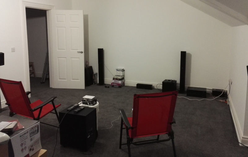
There is a room at the top of my house which was originally earmarked for storage (the loft is full of insulation rather than being a useful option). Then I remembered I still had my pico projector and it ended up as a cinema room as well. The pico projector needs really low light conditions with a long throw, so the fact the room only has a single small window is a plus.
I bought an “N34” mini PC to act as a media player - I already had a spare DVB-T2 stick to Freeview enable things, and the Kodi box downstairs has all my DVDs stored on it for easy streaming. It’s a Celeron N3450 based box with 4G RAM and a 32GB internal eMMC (though I’m currently running off an SD card because that’s what I initially used to set it up and I haven’t bothered to copy it onto the internal device yet). My device came from Amazon and is branded “Kodlix” (whose website no longer works) but it appears to be the same thing as the Beelink AP34.
Getting Linux onto it turned out to be a hassle. GRUB does not want to play with the EFI BIOS; it can be operated sometimes if manually called from the EFI Shell, but it does not work as the default EFI image to load. Various forum posts recommended the use of rEFInd, which mostly works fine.
Other than that Debian Stretch worked without problems. I had to pull in a backports kernel in order to make the DVB-T2 stick work properly, but the hardware on the N34 itself was all supported out of the box.
The other issue was trying to get Wake-on-Lan to work. The room isn’t used day to day so I want to be able to tie various pieces together with home automation such that I can have everything off by default and a scene configured to set things up ready for use. The BIOS has an entry for Wake-on-Lan, ethtool reported Supports Wake-on: g which should mean MagicPacket wakeup was enabled, but no joy. Looking at /proc/acpi/wakeup gave:
/proc/acpi/wakeup contents
Device  S-state   Status   Sysfs node
HDAS      S3    *disabled  pci:0000:00:0e.0
XHC       S3    *enabled   pci:0000:00:15.0
XDCI      S4    *disabled
BRCM      S0    *disabled
RP01      S4    *disabled
PXSX      S4    *disabled
RP02      S4    *disabled
PXSX      S4    *disabled
RP03      S4    *disabled  pci:0000:00:13.0
PXSX      S4    *disabled  pci:0000:01:00.0
RP04      S4    *disabled
PXSX      S4    *disabled
RP05      S4    *disabled
PXSX      S4    *disabled
RP06      S4    *disabled  pci:0000:00:13.3
PXSX      S4    *disabled  pci:0000:02:00.0
PWRK      S4    *enabled   platform:PNP0C0C:00
pci:0000:01:00.0 is the network card:
01:00.0 Ethernet controller [0200]: Realtek […] Ethernet Controller [10ec:8168] (rev 0c)
I need this configured to allow wakeups which apparently is done via sysfs these days:
echo enabled > /sys/bus/pci/devices/0000\:01\:00.0/power/wakeup
This has to be done every boot so I just tied it into /etc/network/interfaces.
All of this then enables Home Assistant to control the Kodi box:
Home Assistant Kodi WoL configuration
wake_on_lan:

media_player:
  - platform: kodi
    name: Kodi (Cinema)
    host: kodi-cinema.here
    port: 8000
    username: kodi
    password: !secret kodi_cinema_pass
    enable_websocket: false
    turn_on_action:
      service: wake_on_lan.send_magic_packet
      data:
        mac: 84:39:be:11:22:33
        broadcast_address: 192.168.0.2
    turn_off_action:
      service: media_player.kodi_call_method
      data:
        entity_id: media_player.kodi_cinema
        method: System.Shutdown
My Home Assistant container sits on a different subnet to the media box, and I found that the N34 wouldn’t respond to a Wake-on-Lan packet to the broadcast MAC address. So I’ve configured the broadcast_address for Home Assistant to be the actual IP of the media box, allowed UDP port 9 (discard) through on the firewall and statically nailed the ARP address of the media box on the router, so it transmits the packet with the correct destination MAC:
ip neigh change 192.168.0.2 lladdr 84:39:be:11:22:33 nud permanent dev eth0
I’ve still got some other bits to glue together (like putting the pico projector on a SonOff), but this gets me started on that process.
(And yes, the room is a bit cosier these days than when that photograph was taken.)
MQTT enabling my doorbell
One of the things about my home automation journey is that I don’t always start out with a firm justification for tying something into my setup. There’s not really any additional gain at present from my living room lights being remotely controllable. When it came to tying the doorbell into my setup I had a clear purpose in mind: I often can’t hear it from my study.
The existing device was a Byron BY101. This consists of a 433MHz bell-push and a corresponding receiver that plugs into a normal mains socket for power. I tried moving the receiver to a more central location, but then had issues with it not reliably activating when the button was pushed. I could have attempted the inverse of Colin’s approach and tried to tie in a wired setup to the wireless receiver, but that would have been too simple.
I first attempted to watch for the doorbell via a basic 433MHz receiver. It seems to use a simple 16 bit identifier followed by 3 bits indicating which tone to use (only 4 are supported by mine; I don’t know if other models support more). The on/off timings are roughly 1040ms/540ms vs 450ms/950ms. I found I could reliably trigger the doorbell using these details, but I’ve not had a lot of luck with reliable 433MHz reception on microcontrollers; generally I use PulseView in conjunction with a basic Cypress FX2 logic analyser to capture from a 433MHz receiver and work out timings. Plus I needed a receiver that could be placed close enough to the bell-push to reliably pick it up.
Of course I already had a receiver that could decode the appropriate codes - the doorbell! Taking it apart revealed a PSU board and separate receiver/bell board. The receiver uses a PT4318-S with a potted chip I assume is the microcontroller. There was an HT24LC02 I2C EEPROM on the bottom of the receiver board; monitoring it with my BusPirate indicated that the 16 bit ID code was stored in address 0x20. Sadly it looked like the EEPROM was only used for data storage; only a handful of values were read on power on.
Additionally there were various test points on the board; probing while pressing the bell-push led to the discovery of a test pad that went to 1.8v when a signal was detected. Perfect. I employed an ESP82661 in the form of an ESP-07, sending out an MQTT message containing “ON” or “OFF” as appropriate when the state changed. I had a DS18B20 lying around so I added that for some temperature monitoring too; it reads a little higher due to being inside the case, but not significantly so.
All of this ended up placed in the bedroom, which conveniently had a socket almost directly above the bell-push. Tying it into Home Assistant was easy:
binary_sensor:
  - platform: mqtt
    name: Doorbell
    state_topic: "doorbell/master-bedroom/button"
I then needed something to alert me when the doorbell was pushed. Long term perhaps I’ll add some sounders around the house hooked in via MQTT, and there’s a Kodi notifier available, but that’s only helpful when the TV is on. I ended up employing my Alexa via Notify Me:
notify:
  - name: alexa
    platform: rest
    message_param_name: notification
    resource: https://api.notifymyecho.com/v1/NotifyMe
    data:
      accessCode: !secret notifyme_key
and then an automation in automations.yaml:
- id: alexa_doorbell
  alias: Notify Alexa when the doorbell is pushed
  trigger:
  - platform: state
    entity_id: binary_sensor.doorbell
    to: 'on'
  action:
  - service: notify.alexa
    data_template:
      message: "Doorbell rang at {{ states('sensor.time') }}"
How well does this work? Better than expected! A couple of days after installing everything we were having lunch when Alexa chimed; the door had been closed and music playing, so we hadn’t heard the doorbell. Turned out to be an unexpected delivery which we’d otherwise have missed. It also allows us to see when someone has rang the doorbell when we were in - useful for seeing missed deliveries etc.
(Full disclosure: When initially probing out the mains doorbell for active signals I did so while it was plugged into the mains. My ‘scope is not fully isolated it seems and at one point I managed to trip the breaker on the mains circuit and blow the ringer part of the doorbell. Ooops. I ended up ordering an identical replacement (avoiding the need to replace the bell-push) and subsequently was able to re-use the ‘broken’ device as the ESP8266 receiver - the receiving part was still working, just not making a noise. The new receiver ended up in the living room, so the doorbell still sounds normally.)
-
I have a basic ESP8266 MQTT framework I’ve been using for a bunch of devices based off Tuan PM’s work. I’ll put it up at some point. ↩
Controlling my heating with Home Assistant
My original post about home automation discussed the fact that one of my motivations was improving control over my central heating system. In the last few weeks I’ve finally brought enough pieces together to make that a reality. My boiler is controlled by a Siemens RCR10/433 thermostat. Ross Harper has a good write-up about decoding the Siemens RCR10/433 and I was able to extend my Energenie Atmel 433MHz transmitter to treat the boiler as another switch. Slightly different timing than the Energenie switches, but exactly the same principle. My TEMPer USB clone provides a reading of the living room temperature. Finally mqtt-arp lets me work out whether anyone is home or not.
Everything is tied together with Home Assistant. The configuration has ended up more involved than I expected, but it’s already better than the old 24 hour timer. There’s definitely still room for improvement in terms of behaviour as the weather starts to get colder and I collect further data. Presently it looks like this:
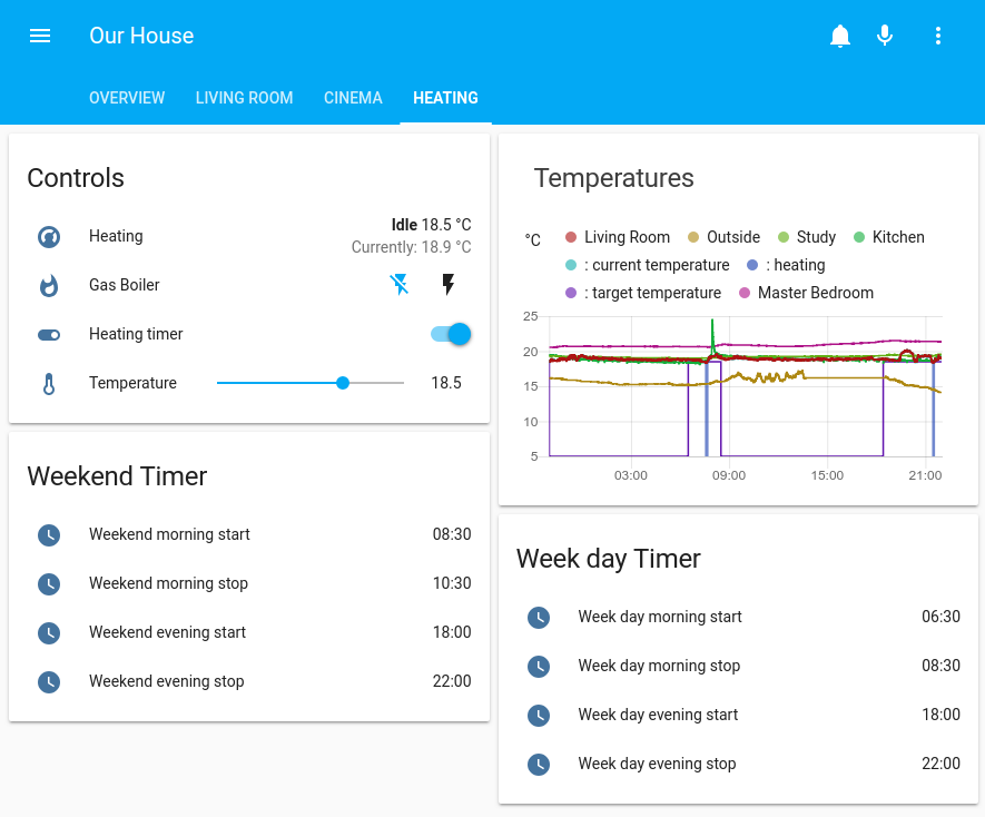
Top left is the control card; “Heating” is a climate control with a target temperature and a current temperature (from the living room sensor), an on/off state for the boiler (linked to the 433MHz transmitter), a switch to indicate if the timer is on or not and finally a slider to control what the target temperature should be when the heating is active.
Top right is a history card showing the various temperature sensors around the house as well as the target temperature state of the heating over the past 24 hours.
The bottom two cards show the timer times for week days and weekends. I did consider making a full 7 day timer, but this ends up good enough and I couldn’t find a better way to represent a set of start + end times that would have allowed a clean interface display of a full week. The times control when the “Heating timer” control in the top left is switched on + off.
These 4 cards provide the ability to see the current state of the heating, and tweak it, ideally meaning there’s no need to hand edit config files during normal operation. Rough theory of operation is:
- If the timer is on and someone is at home, raise the target temperature to the value set in the temperature slider.
- If the timer turns off or everyone leaves the house, lower the target temperature to 5°C.
The core is a generic thermostat:
climate:
  - platform: generic_thermostat
    name: Heating
    heater: switch.gas_boiler
    target_sensor: sensor.living_room_temperature
    min_temp: 5
    max_temp: 25
    ac_mode: false
    hot_tolerance: 0.5
    cold_tolerance: 0.1
    min_cycle_duration:
      minutes: 5
    keep_alive:
      minutes: 30
    initial_operation_mode: 'auto'
This is always active, and climate.set_temperature used to control what the target temperature is.
The temperature control slider is a simple input_number:
input_number:
  heating_temperature:
    name: Temperature
    min: 5
    max: 25
    step: 0.5
    icon: mdi:thermometer
The timer is where it gets complex. There are 8 input_datetime entries to deal with the different start/stop times. It seems like there should be an easier way, but this is what I have:
Heating start/stop time inputs
input_datetime:
  weekday_morning_start:
    name: Week day morning start
    has_time: true
    has_date: false
  weekday_morning_stop:
    name: Week day morning stop
    has_time: true
    has_date: false
  weekend_morning_start:
    name: Weekend morning start
    has_time: true
    has_date: false
  weekend_morning_stop:
    name: Weekend morning stop
    has_time: true
    has_date: false
  weekday_evening_start:
    name: Week day evening start
    has_time: true
    has_date: false
  weekday_evening_stop:
    name: Week day evening stop
    has_time: true
    has_date: false
  weekend_evening_start:
    name: Weekend evening start
    has_time: true
    has_date: false
  weekend_evening_stop:
    name: Weekend evening stop
    has_time: true
    has_date: false
For the automations I also needed to add a time & date sensor:
sensor:
  - platform: time_date
    display_options:
      - 'time'
And finally the output input_boolean to represent if the timer is active or not:
input_boolean:
  heating_timer:
    name: Heating timer
    icon: mdi:toggle-switch
These get tied together with a bunch of automations:
Automations for heating timer
automation:
  - id: heating_morning_on_wd
    alias: Turn heating on (weekday mornings)
    trigger:
      platform: template
      value_template: "{{ states('sensor.time') == (states.input_datetime.weekday_morning_start.attributes.timestamp | int | timestamp_custom('%H:%M', False)) }}"
    condition:
      condition: time
      weekday:
        - mon
        - tue
        - wed
        - thu
        - fri
    action:
      service: input_boolean.turn_on
      data_template:
        entity_id: input_boolean.heating_timer

  - id: heating_morning_off_wd
    alias: Turn heating off (weekday mornings)
    trigger:
      platform: template
      value_template: "{{ states('sensor.time') == (states.input_datetime.weekday_morning_stop.attributes.timestamp | int | timestamp_custom('%H:%M', False)) }}"
    condition:
      condition: time
      weekday:
        - mon
        - tue
        - wed
        - thu
        - fri
    action:
      service: input_boolean.turn_off
      data_template:
        entity_id: input_boolean.heating_timer

  - id: heating_evening_on_wd
    alias: Turn heating on (weekday evenings)
    trigger:
      platform: template
      value_template: "{{ states('sensor.time') == (states.input_datetime.weekday_evening_start.attributes.timestamp | int | timestamp_custom('%H:%M', False)) }}"
    condition:
      condition: time
      weekday:
        - mon
        - tue
        - wed
        - thu
        - fri
    action:
      service: input_boolean.turn_on
      data_template:
        entity_id: input_boolean.heating_timer

  - id: heating_evening_off_wd
    alias: Turn heating off (weekday evenings)
    trigger:
      platform: template
      value_template: "{{ states('sensor.time') == (states.input_datetime.weekday_evening_stop.attributes.timestamp | int | timestamp_custom('%H:%M', False)) }}"
    condition:
      condition: time
      weekday:
        - mon
        - tue
        - wed
        - thu
        - fri
    action:
      service: input_boolean.turn_off
      data_template:
        entity_id: input_boolean.heating_timer

  - id: heating_morning_on_we
    alias: Turn heating on (weekend mornings)
    trigger:
      platform: template
      value_template: "{{ states('sensor.time') == (states.input_datetime.weekend_morning_start.attributes.timestamp | int | timestamp_custom('%H:%M', False)) }}"
    condition:
      condition: time
      weekday:
        - sat
        - sun
    action:
      service: input_boolean.turn_on
      data_template:
        entity_id: input_boolean.heating_timer

  - id: heating_morning_off_we
    alias: Turn heating off (weekend mornings)
    trigger:
      platform: template
      value_template: "{{ states('sensor.time') == (states.input_datetime.weekend_morning_stop.attributes.timestamp | int | timestamp_custom('%H:%M', False)) }}"
    condition:
      condition: time
      weekday:
        - sat
        - sun
    action:
      service: input_boolean.turn_off
      data_template:
        entity_id: input_boolean.heating_timer

  - id: heating_evening_on_we
    alias: Turn heating on (weekend evenings)
    trigger:
      platform: template
      value_template: "{{ states('sensor.time') == (states.input_datetime.weekend_evening_start.attributes.timestamp | int | timestamp_custom('%H:%M', False)) }}"
    condition:
      - condition: time
        weekday:
          - sat
          - sun
    action:
      service: input_boolean.turn_on
      data_template:
        entity_id: input_boolean.heating_timer

  - id: heating_evening_off_we
    alias: Turn heating off (weekend evenings)
    trigger:
      platform: template
      value_template: "{{ states('sensor.time') == (states.input_datetime.weekend_evening_stop.attributes.timestamp | int | timestamp_custom('%H:%M', False)) }}"
    condition:
      condition: time
      weekday:
        - sat
        - sun
    action:
      service: input_boolean.turn_off
      data_template:
        entity_id: input_boolean.heating_timer
The timer boolean switch and the group.all_devices presence information are then tied together to raise/lower the target temperature as appropriate. I’ve used 4 automations for this - one triggered for timer on, one for timer off, one for someone arriving at home, one for everyone leaving. Again, there might be a better way, but this does what I need:
Automations to raise/lower target temperature
automation:
  - id: heating_timer_on
    alias: Turn heating on based on timer
    trigger:
      platform: state
      entity_id: input_boolean.heating_timer
      to: 'on'
    condition:
      condition: state
      entity_id: group.all_devices
      state: 'home'
    action:
      service: climate.set_temperature
      data_template:
        entity_id: climate.heating
        temperature: "{{ states('input_number.heating_temperature') }}"

  - id: heating_timer_off
    alias: Turn heating off based on timer
    trigger:
      platform: state
      entity_id: input_boolean.heating_timer
      to: 'off'
    action:
      service: climate.set_temperature
      data:
        entity_id: climate.heating
        temperature: 5

  - id: heating_on_when_get_home
    alias: Turn heating on on arrival if timer on
    trigger:
      platform: state
      entity_id: group.all_devices
      from: "not_home"
      to: "home"
    condition:
      condition: state
      entity_id: input_boolean.heating_timer
      state: 'on'
    action:
      service: climate.set_temperature
      data_template:
        entity_id: climate.heating
        temperature: "{{ states('input_number.heating_temperature') }}"

  - id: heating_off_when_leave_home
    alias: Turn heating off when we leave home
    trigger:
      platform: state
      entity_id: group.all_devices
      from: "home"
      to: "not_home"
    action:
      service: climate.set_temperature
      data:
        entity_id: climate.heating
        temperature: 5
Finally there’s the UI configuration, which I’ve done using Lovelace. The use of ‘:’ as the name for the climate.heating element is a kludge - I haven’t figured out yet how to name each individual data entry it adds to the history graph. I’m not particularly fond of the input method for controlling times - something closer to the Android analog clock with digits at the top would be nicer, but I’m not a UI guy and this works well enough.
Lovelace configuration for heating controls
views:
  - title: Heating
    cards:
      - type: entities
        title: Controls
        show_header_toggle: false
        entities:
          - climate.heating
          - switch.gas_boiler
          - input_boolean.heating_timer
          - input_number.heating_temperature

      - type: history-graph
        title: Temperatures
        entities:
          - entity: sensor.kitchen_temperature
            name: Kitchen
          - entity: sensor.living_room_temperature
            name: Living Room
          - entity: sensor.master_bedroom_temperature
            name: Master Bedroom
          - entity: sensor.outside
            name: Outside
          - entity: sensor.study_temperature
            name: Study
          - entity: climate.heating
            name: ":"

      - type: entities
        title: Week day Timer
        entities:
          - input_datetime.weekday_morning_start
          - input_datetime.weekday_morning_stop
          - input_datetime.weekday_evening_start
          - input_datetime.weekday_evening_stop

      - type: entities
        title: Weekend Timer
        entities:
          - input_datetime.weekend_morning_start
          - input_datetime.weekend_morning_stop
          - input_datetime.weekend_evening_start
          - input_datetime.weekend_evening_stop
Using ARP via netlink to detect presence
If you remember my first post about home automation I mentioned a desire to use some sort of presence detection as part of deciding when to turn the heat on. Home Assistant has a wide selection of presence detection modules available, but the easy ones didn’t seem like the right solutions. I don’t want something that has to run on my phone to say where I am, but using the phone as the proxy for presence seemed reasonable. It connects to the wifi when at home, so watching for that involves no overhead on the phone and should be reliable (as long as I haven’t let my phone run down). I run OpenWRT on my main house router and there are a number of solutions which work by scraping the web interface. openwrt_hass_devicetracker is a bit better but it watches the hostapd logs and my wifi is actually handled by some UniFis.
So how to do it more efficiently? Learn how to watch for ARP requests via Netlink! That way I could have something sitting idle and only doing any work when it sees a new event, that could be small enough to run directly on the router. I could then tie it together with the Mosquitto client libraries and announce presence via MQTT, tying it into Home Assistant with the MQTT Device Tracker.
I’m going to go into a bit more detail about the Netlink side of things, because I found it hard to find simple documentation and ended up reading kernel source code to figure out what I wanted. If you’re not interested in that you can find my mqtt-arp (I suck at naming simple things) tool locally or on GitHub. It ends up as an 8k binary for my MIPS based OpenWRT box and just needs fed a list of MAC addresses to watch for and details of the MQTT server. When it sees a device it cares about make an ARP request it reports the presence for that device as “home” (configurable), rate limiting it to at most once every 2 minutes. Once it hasn’t seen anything from the device for 10 minutes it declares the location to be unknown. I have found Samsung phones are a little prone to disconnecting from the wifi when not in use so you might need to lengthen the timeout if all you have are Samsung devices.
Home Assistant configuration is easy:
device_tracker:
  - platform: mqtt
    devices:
      noodles: 'location/by-mac/0C:11:22:33:44:55'
      helen: 'location/by-mac/4C:11:22:33:44:55'
On to the Netlink stuff…
Firstly, you can watch the netlink messages we’re interested in using iproute2 - just run ip monitor. Works as an unpriviledged user which is nice. This happens via an AF_NETLINK routing socket (rtnetlink(7)):
int sock;
sock = socket(AF_NETLINK, SOCK_RAW, NETLINK_ROUTE);
We then want to indicate we’re listening for neighbour events:
struct sockaddr_nl group_addr;
bzero(&group_addr, sizeof(group_addr));
group_addr.nl_family = AF_NETLINK;
group_addr.nl_pid = getpid();
group_addr.nl_groups = RTMGRP_NEIGH;
bind(sock, (struct sockaddr *) &group_addr, sizeof(group_addr));
At this point we’re good to go and can wait for an event message:
received = recv(sock, buf, sizeof(buf), 0);
This will be a struct nlmsghdr message and the nlmsg_type field will provide details of what type. In particular I look for RTM_NEWNEIGH, indicating a new neighbour has been seen. This is of type struct ndmsg and immediately follows the struct nlmsghdr in the received message. That has details of the address family type (IPv6 vs IPv4), the state and various flags (such as whether it’s NUD_REACHABLE indicating presence). The only slightly tricky bit comes in working out the MAC address, which is one of potentially several struct nlattr attributes which follow the struct ndmsg. In particular I’m interested in an nla_type of NDA_LLADDR, in which case the attribute data is the MAC address. The main_loop function in mqtt-arp.c shows this - it’s fairly simple stuff, and works nicely. It was just figuring out the relationship between it all and the exact messages I cared about that took me a little time to track down.
PSA: the.earth.li ceasing Debian mirror service
This is a public service announcement that the.earth.li (the machine that hosts this blog) will cease service as a Debian mirror on 1st February 2019 at the latest.
It has already been removed from the official list of Debian mirrors. Please update your sources.list to point to an alternative sooner rather than later.
The removal has been driven by a number of factors:
- This mirror was originally setup when I was running Black Cat Networks, and a local mirror was generally useful to us. It’s 11+ years since Black Cat was sold, and 7+ since it moved away from that network.
- the.earth.li currently lives with Bytemark, who already have an official secondary mirror. It does not add any useful resilience to the mirror network.
- For a long time I’ve been unable to mirror all release architectures due to disk space limitations; I think such mirrors are of limited usefulness unless located in locations with dubious connectivity to alternative full mirrors.
- Bytemark have been acquired by IOMart and I’m uncertain as to whether my machine will remain there long term - the acquisition announcement focuses on their cloud service rather than mentioning physical server provision. Disk space requirements are one of my major costs and the Debian mirror makes up ⅔ of my current disk usage. Dropping it will make moving host easier for me, should it prove necessary.
I can’t find an exact record of when I started running a mirror, but it was certainly before April 2005. 13 years doesn’t seem like a bad length of time to have been providing the service. Personally I’ve moved to deb.debian.org but if the network location of the is the reason you chose it then mirror.bytemark.co.uk should be a good option.
subscribe via RSS