Making my first PCB
I’ve written a lot about my various home automation bits, but I haven’t generally posted pictures. That’s because my construction skills aren’t great; I’m wiring together modules and that tends to make it harder to case things properly and make them look nice. My first attempt to be better about this was to buy a prototyping box which had a case + board paired with it I could attach modules to. This helped a bit, but still involved a mess set of wiring to attach things together (proper strip board would have been more useful than just copper pads).
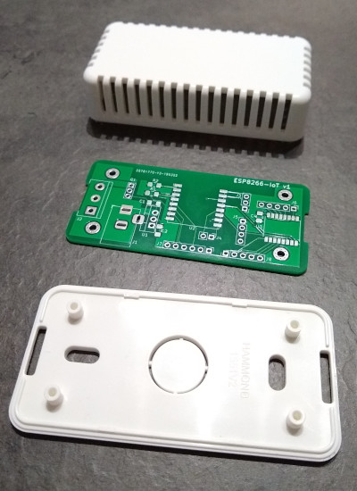
I then started to notice I was getting JLCPCB ads while web browsing, offering 10 PCBs for $2. That seemed like a good deal, and I thought if I did things right I could find the right case and then make sure the PCB fitted in it. I found a small vented white case available from CPC. This allows me to put a temperature sensor inside for some devices. KiCad seemed like a good option for trying to design my basic schematic and lay it out, so I installed it and set to work trying to figure out what I wanted to put on the board, and how to actually drive KiCad.
As the core I chose an ESP-07 ESP8266 module. I’ve used a few of them before and they’re cheap and convenient. I added an LDO voltage regulator (LD1117) so I could use a 5V PSU (and I’m hoping with a heatsink I can get away with a 12V supply as well, even if it’s more inefficient). That gave enough to get a basic schematic once I’d added the necessary pull-up/down resistors for the ESP8266 and decoupling capacitors. I included a DC barrel jack for the PSU, and pin headers for the serial port, SPI pins and GPIO0 for boot selection. One of my use cases is to make an LED strip controller, so I threw in a screw terminal block for power + control - the board is laid out to allow a MOSFET for a simple white 12V LED strip, or the same GPIO taken straight to the terminal block for controlling a WS2812 strip. By including a couple of extra pull-up resistors I added the option of I2C for further expansion.
After I had the basic schematic I moved to layout. Luckily Hammond provide 2D CAD files for the case, so I figured I would import them into KiCad’s PCB layout tool to make sure things would fit. That took a little bit of effort to go from DWG to DXF and trim it down (I found a web tool to do the initial conversion and then had to strip out the bits of the case that weren’t related to the PCB size + mounting points). I wasn’t confident enough that the edge cuts layer would include the mounting holes, so I manually placed some from KiCad over the right spots.
At this point I was glad I had a simple design, because it took me a while to decide how to place things and then route the tracks. I ended up altering some header pin assignments from the original design to make things a bit easier to route, and took advantage of the double sided board to put some components underneath, to ease both routing and space constraints. Originally I had planned to make things easy and go for through-hole components (I’ve never SMD soldered before) but in the interests of making use of space I risked the “1206 Handsoldered” footprint option in KiCad, which seems to be like the Duplo of SMD components. I kept my regulator as through-hole to make a larger heatsink easier. I also discovered I had a bit of spare space, so I put down a footprint and pin headers for a PCF8574 I2C GPIO expander to allow for more IO if I needed it. Finally the I2C pin header was laid out to allow a BME280 module to be soldered directly on top, allowing for easy addition of environmental monitoring without having to solder ridiculously small devices myself.
Once I had all of that done I printed out my final design, carefully cut around the edge and made sure it fitted into the case and the components I already had where the right size. Once I was fairly confident I’d checked as much as I could I then did a Gerber export and uploaded to JLCPCB. The process was very smooth - you upload a zip file, can do a sanity check viewing of how they’ve parsed it, select various options for the PCB (I left almost everything as the default) and then submit the order. Over the next couple of days you can see things progress through the various manufacturing stages and then get dispatched. For the first order it turns out you get free DHL Express delivery, so I ordered on Friday morning and had 10 boards by Wednesday afternoon. All for £1.58. A friend tells me subsequent orders have standard China Post shipping as standard, but for that price it’s still hard to beat!
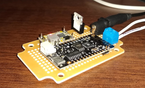
How did they turn out? Pretty well. The quality of the boards is excellent to my untrained eye. Soldering the SMD bits got easier when I switched to a better bit on my soldering iron and made sure it was well screwed in (otherwise it, er, doesn’t heat up particularly reliably) - my soldering is still terrible, but it gets the job done. Most importantly the PCB fit the case footprint perfectly - mounting holes in the right place, edge cuts the right shape/size. A couple of snips to the vents and the barrel jack connector and terminal block are easily accessible, and it still looks fairly neat. The main mistake I made was not thinking about component heights! In particular the barrel jack was a couple of mm too high, which a quick shave with a Dremel sorted. The voltage regulator also stood far too high, which I fixed by bending at a 90° angle over the board. This will limit my options for a heatsink, but for 5V power this isn’t necessary anyway.
So far I’ve assembled 2 boards, both controlling WS2812 LED strips and powered by 5V PSUs. One also has a BME280 added. I’m waiting on more parts arriving and then will try out a 12V / white LED strip combo. I’m really pleased with the overall results; it took a while playing with KiCad to get to the point I was confident to send my files off to be manufactured (the print outs helped a lot), and failing to think about component heights was a silly mistake, but having everything mounted on a single PCB and firmly screwed into a case makes for a much more robust project. The first 2 are both hidden out of the way, but it’s reassuring to know they’re not particularly fragile like some of my earlier constructions. And I’m already trying to work out what PCB I want to make next…