home :: techie :: projects :: LCD :: LCDProject.txt
Serial port LCD display
Intro
I want a little device for controlling a computer without all the requirements of a monitor. Monitors are big and bulky and currently look quite ugly. When LCD monitors become really really cheap, then they will be the solution. Unfortunately this might take some time.
Having looked at the cute cases that you can get for the tiny mini-ITX motherboards. I was toying with the idea of having a computer hidden in my bedroom as a gateway to my music collection, and to my emails/little notes. It wouldn't be very hidden if there was a great big monitor sitting there, so I thought that the ability to control it (at least most of the time) without a monitor would be good. LCD seemed the way to go.
Parts
I spent time browsing Maplin and RS Components websites, and saw little LCD displays, that were (apparently) easy to program. That sounded ideal.
Even better, I found a bit of hardware that would allow me to control the display over the serial port, rather than by twiddling bits on a parallel port (though there is drivers to do the bit-fiddling for me). This apealed to my sense of what is right, as you shouldn't really need 10 wires from a computer to control a little LCD display.
RS Stock codes.
424-7231, SAPIC-B serial interface. (Note, the description on the site is for the SAPIC-E, which you do not get. You get the SAPIC-B)
294-8774, 16×2 STN LCD Display with backlight.
Total cost with VAT 40 quid. Yes, it is a lot.
Construction
It really was not to difficult to make this. I needed power and data from the computer, and a ribbon cable between the serial interface and the LCD display.
It turned out that a really old bit of ribbon cable from my bits box even had the right-sized IDC connector on the end to simply connect to the pins on the output of the interface. This just needed about 5 or 6 of its wires soldering to the bottom of the display.
Power was from the game port. The connector and cable being donated by an old, broken joystick. The game port's power lines tend to be connected directly onto the motherboard's +5V line and can draw several amps easily. In this case the display and backlight need about 120ma so no problems there.
Data came from an old mouse, the two data lines being connected to the correct ports on the interface. My soldering is not perfect (as you can see from the photos), and I did discover that soldering really requires about 4 hands if you want to actually join two bits of wire together.
Boxing it up
Well, at this point I had a working display, with working backlight, but it was sitting on my desk, with every chance that the next time I movem my mouse it would knock the slightly dodgy soldering apart. Well, I didn't want that, as it is a pain in the arse to solder it back together unless you have 4 hands.
What can I use for a box for a screen. Well, eventually I expected that it would be some wood or plastic affair. However I just wanted to get everything up and running so that I could go to bed, or at least stop playing with this.
I remembered that I had some little cardboard boxes that I was planning to use for minidisc storage. One of them was the right sort of size, and would provide protection for my dodgy soldering.
Images
|
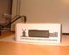
So, here it is in all its glory. It even is displaying the time and date. Unfortunately you cannot see the back light in this picture. |
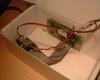
| The insides are slightly less glorious. Here you can clearly see the two boards that make up the whole thing, and the cables joining them. |
|
Future
I think that the next part of the project will be to convert it to be powered from USB rather than the joystick port. The machine on which it was intended to be used has USB by no joystick port, and the current required to power the backlight is easily covered by USB.
A smaller, flashier box will probably occur too. Part of installing it in the new box will be to tidy up the soldered connections.
Finally I think that I should get around to finishing writing software for it. Currently I only have scripts that display load and the time on the display. It must have quite a few other uses.
Wiring Notes
Joystick connector, Green Power, Black Ground.
Mouse: Red ground, Black RD, Brown TD, Orange CTS
Links
Joystick port pinout(no longer exists, google for it)Manufacturers Web sitefor the serial controller.- RS Components where I bought the parts.
Last updated: 23:41, 24 Aug 2003 Link..